3 Assembly instructions, storage, preparation, installation
B 1050 en-1819 47
Pos: 88 /Anleitungen/Getriebe/3. Montage, Lagerung, Vorbereitung, Aufstellung/Drehmomentstütze [B1050_B2050] @ 28\mod_1551192590566_388.docx @ 2491630 @ 2 @ 1
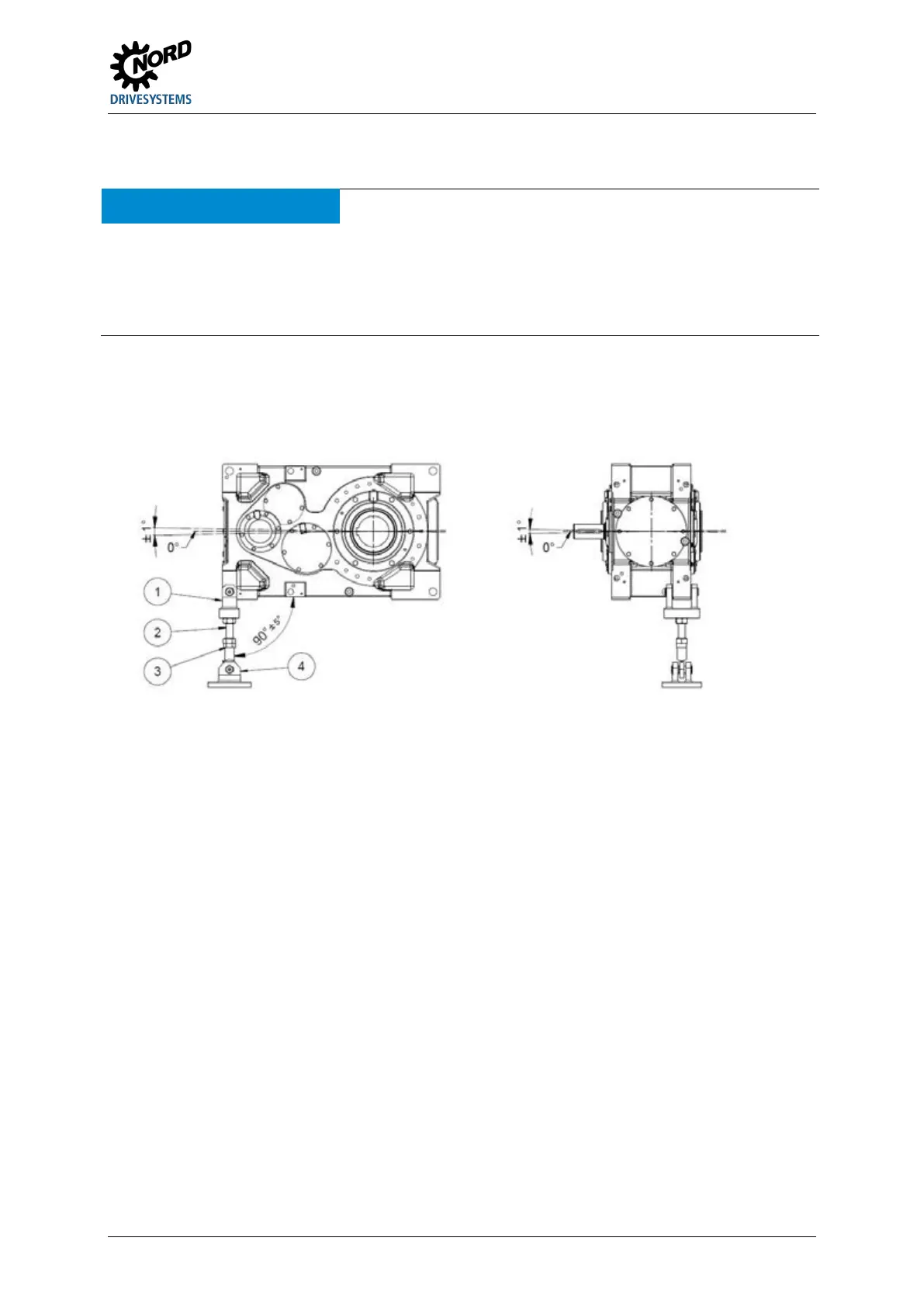
3.18 Torque supports (Option: D, ED, MS)
NOTICE! Gear unit damage
Failure to observe the following points may cause damage to the gear unit:
• Distortion of the torque support during assembly or operation must be avoided, as otherwise the service life of
the output shaft bearings may be reduced.
• The torque support is not suitable for transferring transverse forces.
Assembly should be carried out from the side of the machine, in order to reduce the bending moment
on the machine shaft. Tension and pressure and installation upwards or downwards are permissible.
For helical gear units with motor adapters, the torque support is located opposite to the motor adapter.
Explanation
Maintenance-free joint head
Figure 19: Permissible installation tolerances of the torque support (Option D and ED) (schematic
diagram)
The length of the torque support (Option: D) can be adjusted within a certain range.
The gear unit is aligned horizontally by means of the threaded bolt and the nuts of the torque support
and secured with lock-nuts.
Tighten the fastenings of the torque support with the correct tightening torques (7.4 "Torque values")
and secure against loosening (e.g. Loctite 242, Loxeal 54-03).
The Option ED torque support has an integrated elastic element and cannot be adjusted in length.
Pos: 89 /A llg em ein/ Allg em eing ülti ge M od ule/ ---------Seite numbruc h kom pakt --------- @ 13\ mod_1476369695906_0.docx @ 2265495 @ @ 1
 Loading...