3 Assembly instructions, storage, preparation, installation
B 1050 en-1819 43
Pos: 79 /Anl eitung en/Ge trie be/3. Mo ntage , Lager ung, Vorberei tung , Aufst ellu ng/Int erne Kü hlanl age_ 01_(Mo ntag e) [B1 050, B20 50] @ 28 \mod_1551191715764_388.docx @ 2491593 @ 2 @ 1
3.15 Internal cooling system (Option: CC)
Pos: 80 /A nl eitu nge n/G etr iebe /3. Mont ag e, L ager ung, Vor berei tung, Aufst ellung /Inter ne Kü hlanlag e_03 _(Mo ntage) [B105 0, B205 0] @ 30\mod_1552923920049_388.docx @ 2511108 @ @ 1
Risk of injury
Possibility of injury due to pressure discharge.
• Ensure that the pressure is released from the cooling circuit before carrying out any work on the gear unit.
For the inlet and outlet of cooling fluid, connections with pipe threads are provided on the gear unit or
the casing cover for fitting pipes or hoses. The exact size of the pipe thread can be obtained from the
specific dimension sheet for the order.
Remove the drain plug from the screw neck prior to assembly to avoid any contamination of
the cooling system. The screw necks should be connected with the coolant circuit, which must be
provided by the operator. The flow direction of the coolant is irrelevant.
NOTICE!
Gear unit damage
Do not twist the connections during or after assembly as otherwise the cooling coil may be damaged.
• It must be ensured that no external forces act on the cooling coil.
• Vibrations must be avoided (fatigue fracture)
If a volume regulator is fitted upstream of the cooling coil, the connection is extended accordingly. The
cooling water must be fed in via the volume regulator. Observe the operating instructions of the
volume regulator.
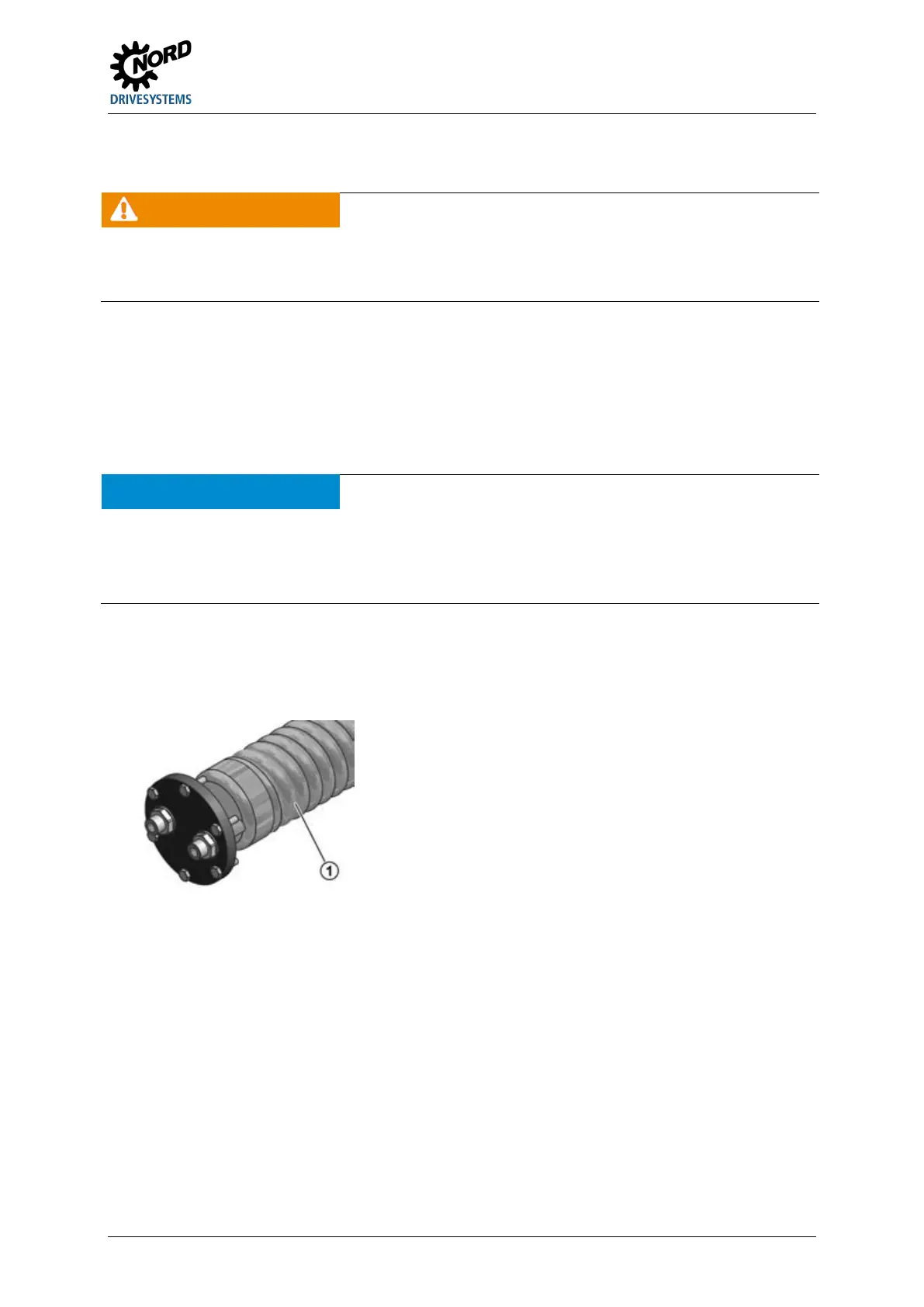
Figure 16: Cooling cover with cooling coil fitted (schematic diagram)
Pos: 81 /A llg em ein/ Allg em eing ülti ge M od ule/ ---------Seite numbruc h kom pakt --------- @ 13\ mod_1476369695906_0.docx @ 2265495 @ @ 1
 Loading...