5. Service and Maintenance
-22- B1000 www.nord.com
Checking the oil level:
1. The oil level may only be checked when the gear unit is at a standstill and has cooled
down. The gear unit must be secured to prevent accidental switch-on.
2. The oil level screw corresponding to the version must be screwed out. (See Section 6.1)
Note!
At the first oil level check a small amount of oil may escape, as the oil level may be below the
lower edge of the oil level hole.
3. Gear units with oil level screw: The maximum oil level is the lower edge of the oil level hole.
The minimum oil level is 4 mm below the oil level hole. If the oil level is too low, this must be
corrected using the correct type of oil. An oil level glass is available instead of the oil level
screw
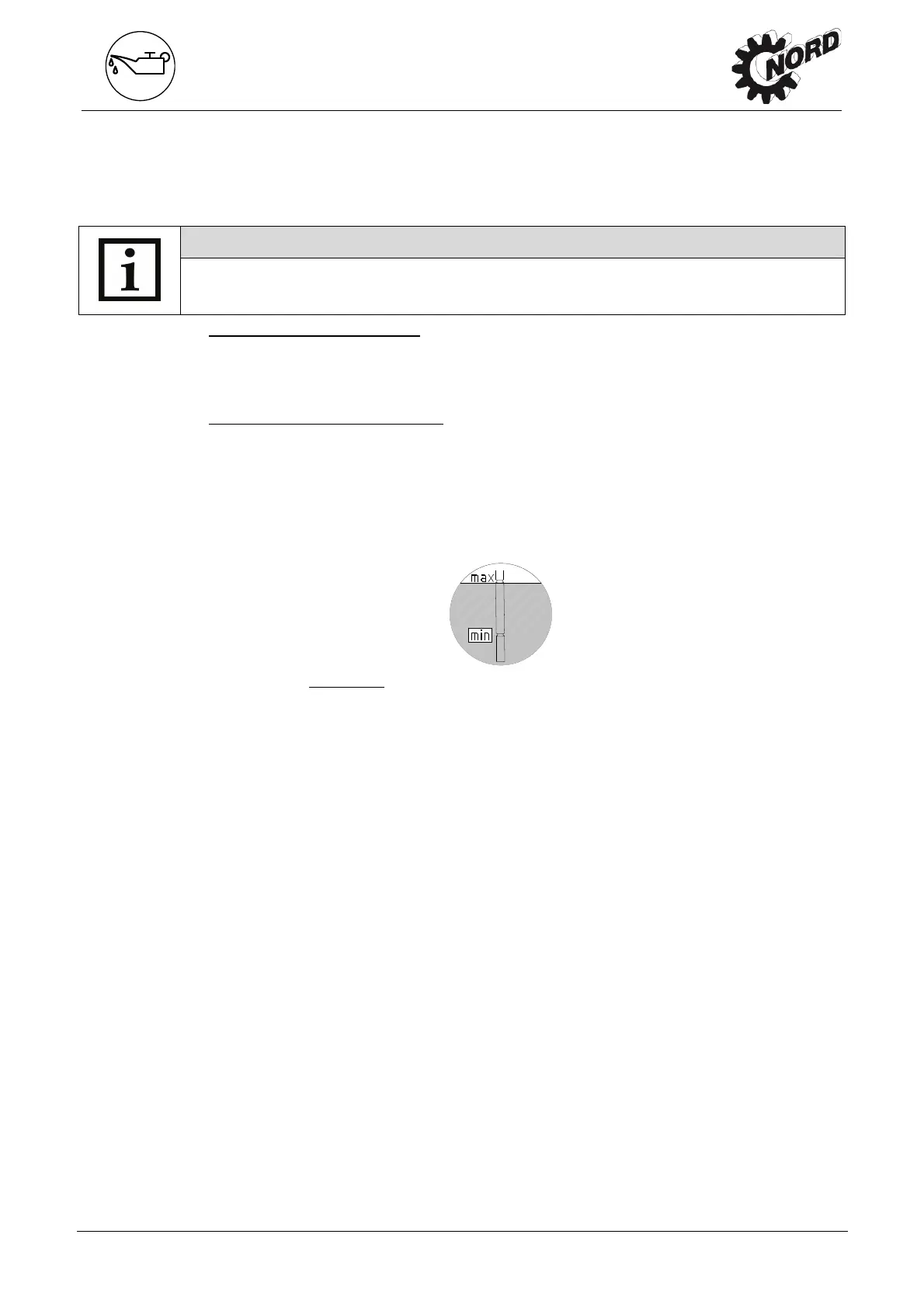
4. Gear units with an oil level vessel:
The oil level must be checked in the oil level vessel with
the aid of the dipstick plug (thread G1 1/4). The oil level must be between the upper and
lower mark when the dipstick is completely screwed in (see Fig. 5-1). The oil level must be
corrected with the correct type of oil if necessary. These gearboxes may only be operated in
the configuration stated in Section 6.1.
5. The oil level screw or the cap screw with dipstick and all other loosened screws must be
correctly re-tightened.
Figure 5-1:
Check the oil level with a dipstick
Regreasing
Some gear unit designs (free drive shaft, Option W, agitator designs VLII and VLIII) are
equipped with a regreasing device.
For agitator versions VLII and VLIII, the vent screw located opposite to the grease nipple must
be unscrewed before regreasing. Grease should be injected until a quantity of 20-25g escapes
from the vent hole. After this, the vent plug must be reinserted and tightened.
For Option W and some IEC adapters, the outer roller bearing must be regreased with approx.
20-25g of grease via the grease nipple provided
Recommended grease: Petamo GHY 133N (see Section 6.4: Klüber Lubrication).
Replacing the automatic lubricant dispenser
Screw-off the cartridge case cover (2), (see Fig. 4-1). The lubrication dispenser (5) is screwed
out and replaced with a new component (Part No. 283 0100). Then activate (see Chapter 4.2)!
Changing the oil
The figures in Section 6.1 show the oil drain screw, the oil level screw and the pressure vent
screw for various designs.
Sequence:
1. Place the drip tray below the oil drain screw
2. Completely remove oil level screw, screwed sealing plug with dipstick if an oil level tank
is being used and oil drain screw.
 Loading...