9
Communicating with the board
Unless you programmed a very simple application, you probably want to connect to the board from your
computer to display logging information or send input. You can use Real Time Transfer (RTT) or Universal
Asynchronous Receiver/Transmitter (UART) for communicating with the board.
SEGGER Real Time Transfer (RTT) is a proprietary technology for bidirectional communication that
supports J-Link devices and ARM-based microcontrollers. The advantage of using RTT is that it is very
efficient and does not require any other peripheral than the J-Link debugging interface. RTT is directly
supported in SES.
Connecting via UART is quick and power-efficient, but it requires dedicated use of the UART peripheral for
logging. The nRF5 DKs and the nRF51 Dongle include a UART to USB CDC ACM bridge, which is needed to
connect to the UART. Alternatively, you can use an external UART to USB bridge. We use the term CDC-
UART to refer to UART communication through the UART to USB CDC ACM bridge, to distinguish it from
communication through the Nordic UART Service (NUS) over Bluetooth Low Energy.
9.1 Connecting via RTT
SES directly supports RTT. You can see RTT output in the Debug Terminal during debugging sessions.
Alternatively, you can use J-Link RTT to view RTT output. See the following sections for instructions for
Windows and Linux.
9.1.1 Connecting via RTT on Windows
To communicate via RTT, connect your development board via USB and run the J-Link RTT Viewer.
Note: SES natively supports RTT. If enabled, the monitor shows up when you start debugging.
Alternatively, you can use SEGGER's J-Link RTT Viewer as described below.
The J-Link RTT Viewer is installed as part of the nRF5x Command Line Tools.
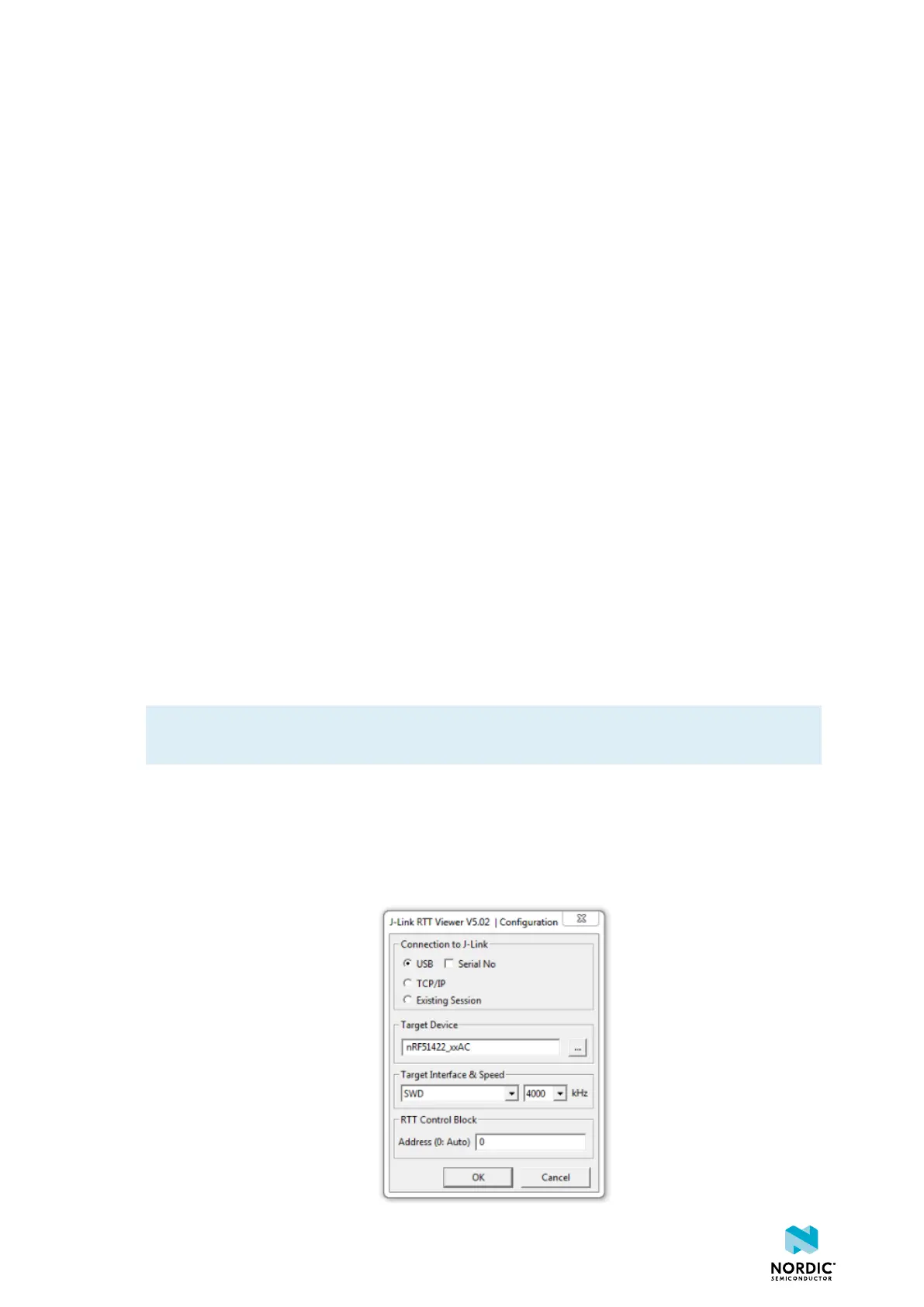
To run the J-Link RTT Viewer on Windows, complete the following steps:
1. Select the correct target device.
The target device is represented by the ID of your development board.
2. Select SWD as the target interface.
1159720_163 v1.1
27
 Loading...