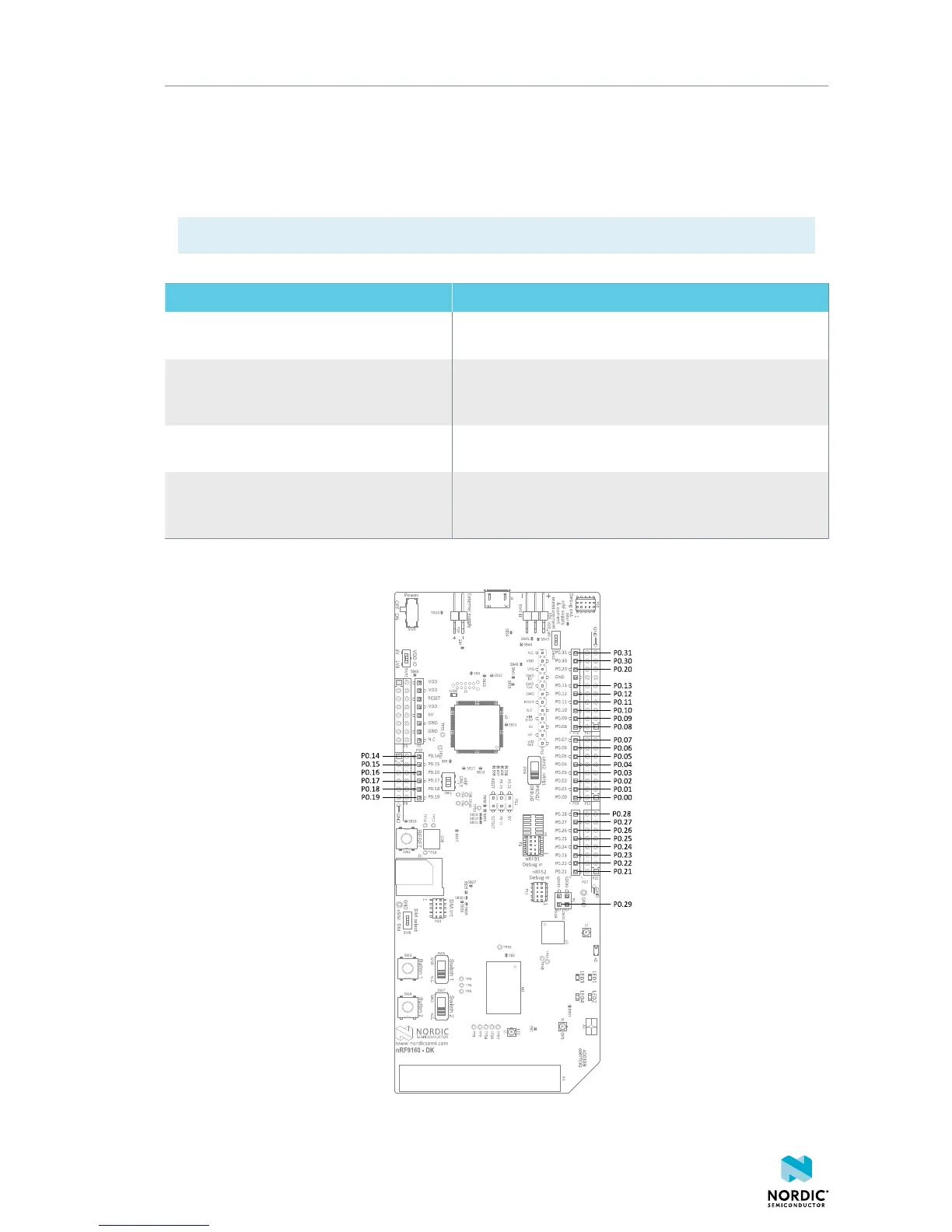
Hardware description
GPIO signals are also available on connectors P5, P6, P12, P17, and P25, which are on the bottom side
of the board. By mounting pin lists on the connector footprints, the nRF9160 DK board can be used as a
shield for Arduino motherboards.
For easy access to GPIO, power, and ground, the signals can also be found on the through-hole connectors
P8, P12, P17, and P25.
Note: GPIO P0.29 is not available on any through-hole connector.
GPIO nRF9160 DK Function
P0.00, P0.01, P0.14, and P0.15 Used as a second UART connection to the interface MCU.
For more information, see Virtual COM port on page 8.
P0.02, P0.03, P0.04, P0.05, P0.06, P0.07,
P0.08, and P0.09
Connected by default to buttons, slide switches, and LEDs.
For more information, see Buttons, slide switches, and
LEDs on page 22.
P0.17, P0.18, P0.19, P0.21, P0.22, P0.23,
COEX0, COEX1, and COEX2
Used to connect the nRF9160 to the nRF9160 DK board
control on page 19.
P0.26, P0.27, P0.28, and P0.29 Used as the primary UART connection to the interface
MCU. For more information, see Virtual COM port on page
8.
Table 3: Default pin settings
Figure 14: nRF9160 DK pins
4418_1216 v0.7
18
 Loading...