Hardware description
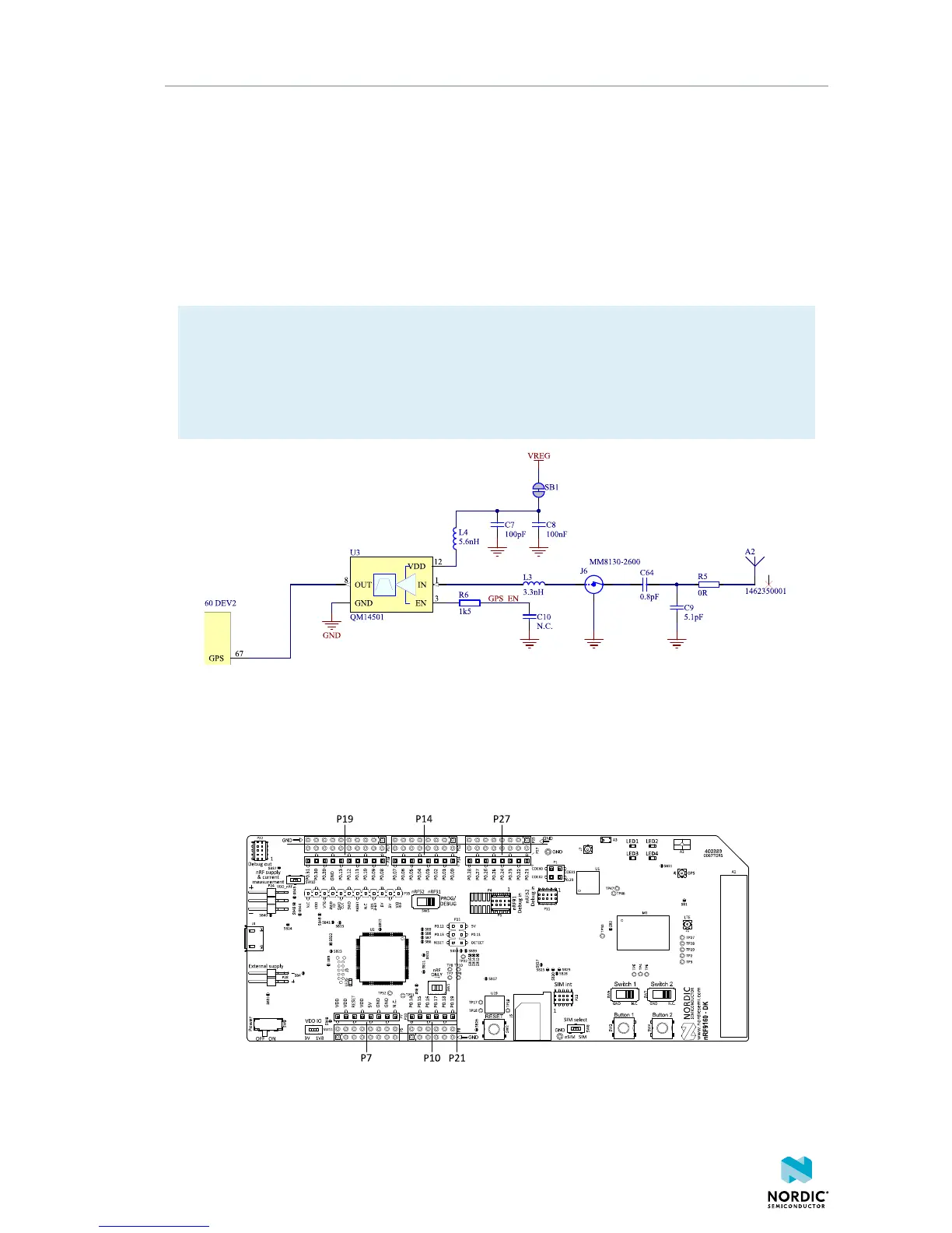
5.5 GPS
The nRF9160 has a dedicated GPS port to support global navigation.
The GPS signal is received in the GPS antenna (A2). The user can connect an external GPS antenna to
connector J6. Connecting an external antenna to J6 automatically disconnects the RF path to A2.
The signal is next amplified and filtered in the combined LNA and BPF U3 before it is fed to the nRF9160.
This makes the GPS receiver more sensitive to GPS signals and less sensitive to interference from other
sources on the DK or nearby.
Note:
• GPS signals do not usually penetrate the ceiling or other structures that well. Therefore, for best
GPS performance, the DK should be placed on a flat surface in an open space outside, far from
sources of interference and other structures that may block the signals from space.
• This functionality is only available if the modem firmware used in the nRF9160 supports GPS.
Figure 12: GPS connected to the nRF9160
5.6 GPIO interfaces
Access to the nRF9160 GPIOs is available from connectors P7, P10, P14, P19, and P27. The nRF9160 DK
supports the Arduino UNO interface.
Figure 13: Access to nRF9160 GPIOs
4418_1216 v0.7
17
 Loading...