Hardware description
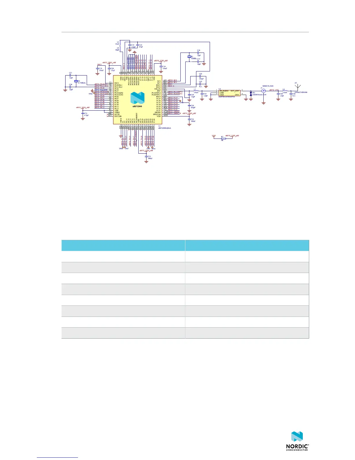
Figure 16: nRF52840 board controller
5.8 Buttons, slide switches, and LEDs
The nRF9160 DK board has four LEDs, two buttons, and two switches for simple user interaction. By
default, they are connected to nRF9160 GPIOs as shown in the following table.
To change default nRF9160 GPIO connections, see nRF9160 DK board control on page 19
Part GPIO
LED 1 P0.02
LED 2 P0.03
LED 3 P0.04
LED 4 P0.05
Button1 P0.06
Button2 P0.07
Switch1 P0.08
Switch2 P0.09
Table 5: Button and LED connection
The nRF52840 can be used to disconnect any of the LEDs, slide switches, or buttons.
The buttons and switches are active low, meaning that the input will be connected to ground when the
buttons are pushed or switches slid to the GND position. The buttons and switches have no external pull-
up resistor, and therefore the P0.06, P0.07, P0.08, and P0.09 pins must be configured as an input with an
internal pull-up resistor.
The LEDs are active high, meaning that writing a logical one ('1') to the output pin will illuminate the LED.
The nRF9160 GPIOs control power transistors and LEDs are fed from a separate 3.3 V domain. Therefore,
LED current will not be drawn from nRF9160 GPIOs or the nRF9160 supply.
4418_1216 v0.7
22
 Loading...