6
Measuring current
The current drawn by the nRF9160 can be monitored on the nRF9160 DK board.
Current can be measured using various test instruments, each with advantages and disadvantages.
Examples of test equipment are the following:
• Power analyzer
• Oscilloscope
• Ampere-meter
Connector P24 can be used for measuring current consumption or monitoring voltage levels to the
nRF9160.
The use of a USB connector is not recommended for powering the board during current measurements
due to potential noise from the USB power supply. Instead, the board should be powered by connecting a
power supply to connector P28.
For more information on measuring, see sections Using an oscilloscope for current profile measurement
on page 32 and Using a current meter for current measurement on page 32.
6.1 Preparing the development kit for current
measurements
To measure the current consumption of the SiP, you must first prepare the board.
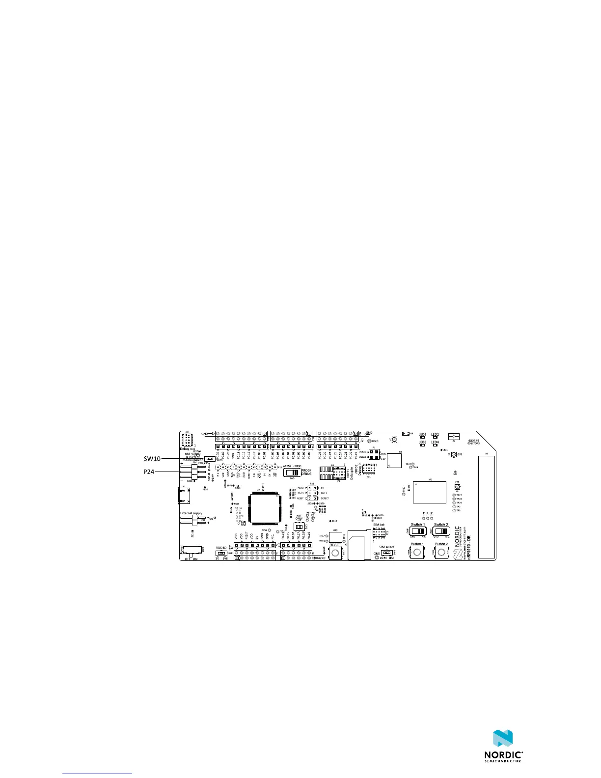
1. Slide switch SW10 to the EXT position to disable switch U25.
This cut disconnects the nRF9160 from the power management circuitries on the board.
Figure 26: Solder bridges SB44 and SB45 on the nRF9160 DK board
2. To restore normal kit functionality after measurement, slide switch SW10 back to the default position
INT or apply a jumper on P24 by shorting the two uppermost pins as shown in the figure above.
4418_1216 v0.7
31
 Loading...