Description
A 2-5
Part 331235C
E 2003 Nordson Corporation
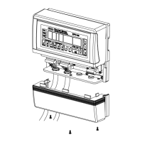
Part A: System Overview
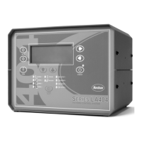
Display
See Figure A 2-3 and refer to Table A 2-3. The display contains the status
of the powder spray, electrostatics, and the set points.
1400378A
1 2
3
5
6
7
8
9
10
11
4
Figure A 2-3 Front Panel Display
Table A 2-3 Front Panel Display
Item Component Description
1 Select Charge Value Indicates which Select Charge value is currently active.
Number range is from 1 to 3.
2 F1/F2 Flow 1/Flow 2 Systems Only: Indicates which flow rate
setting is active.
3 Powder Icon Indicates that guns are triggered and powder flow is on. This
icon will flash if an error in the solenoid circuit is detected.
4 Digital Display Shows the digital number of the set point and actual
parameter information. Additional information that may be
shown is gun on hours, total hours, error codes, kV set point,
A set point, and actual A value. The display is blank when
no appropriate value can be displayed.
5 Gun kV or Electrostatics
Icon
Lights to indicate that the selected gun is triggered. The icon
will flash if an error in a gun drive circuit is detected.
6 Purge Icon Lights to indicate that the gun purge function is active.
7 Unit Indicators Lights to indicate the selection of KV, A, HRS, x10, or
ALARM.
8 Bar Graph Units Shows the unit of measure displayed on the bar graph.
9 Bar Graph Shows the parameter displayed on the digital display as a bar
graph. The bar graph is only active while a gun is triggered.
10 Fault Icon Lights when there is an alarm or error condition. This icon will
not turn off until the unit is reset or all errors are cleared.
11 Diagnostics Icon Lights when the system is in the diagnostics mode.
 Loading...