Installation
A 3-2
Part 331235C
E 2003 Nordson Corporation
Part A: System Overview
Electrical Connections
NOTE: Input power to the modular gun control system must be
85−240 Vac, 1 phase, 50/60 Hz.
1. Install a fused, locking disconnect switch in the service line ahead of the
modular gun control system so that power can be shut off during
installation or repair.
WARNING: All electrically conductive equipment in the spray area must be
connected to a true earth ground. Ungrounded or poorly grounded
equipment can store an electrostatic charge that can give personnel a
severe shock or arc and cause a fire or explosion.
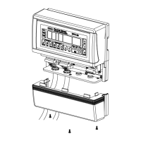
2. See Figure A 3-2. Use the provided ground strap to connect the main
control cabinet ground stud (7) to a true earth ground.
3. The main electrical line (6) shipped with the modular gun control system
is 6 m (20 ft) long. Cut the outer conduit to the desired length. Leave
the wire leads 0.3 m (1 ft) longer than the outer conduit.
4. Install a water-tight strain relief in a knockout in the booth’s main
electrical panel. Route the modular gun control system main electrical
wiring through the strain relief.
5. Refer to Table A 3-1. Connect the leads to the booth’s main electrical
panel using the information listed in Table A 3-1.
6. Connect the the gun cables to the cable receptacles on the gun
receptacle panel (4).
NOTE: Sure Coat automatic gun cables connect directly to the modular
gun control system. Versa-Spray and Tribomatic gun cables require an
adapter between the cable and the modular gun control system. If you
did not receive the necessary adapters, contact your Nordson
representative.
Table A 3-1 Power Supply Wiring
Wire Color Function
Yellow Alarm (normally-open relay contact)
Yellow Alarm (normally-open relay contact)
Brown L1 (hot) interlocked to spray booth fan
Black
1
AUX L1 (hot) not interlocked
Blue L2 (neutral)
Green/Yellow Chassis ground
Red
2
120 V Conveyor interlock
Orange
2,
3
120 V Conveyor interlock
NOTES:
1. The black wire was added to recent revisions and is not present on all systems.
2. The conveyor interlock voltage can be switched from 120 V to 240 V. Refer to Changing Interlock
Voltage from 120V to 240V in this section.
3. The orange wire provided hot, not interlocked power to the application/triggering controller in some
versions of the system. To check which wire is AUX L1, remove the main I/O panel. If the orange
wire is connected to the I/O panel’s power switch, then the orange wire is AUX L1.
 Loading...