Parts
A 7-2
Part 331235C
E 2003 Nordson Corporation
Part A: System Overview
System Components and Hardware
The following lists detail the major system components and hardware.
Refer to the lists later in this section for a breakdown of each subassembly.
NOTE: Your system may not require all of the parts shown.
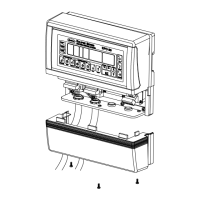
Front
See Figure A 7-1.
Item Part Description Quantity Note
1 334813 CAP, tapped hole, 6 mm, nylon AR
2 - - - - - - CONTROL UNIT, central 1 A
3 - - - - - - BRACKET, mounting, spacer 2
4 303099 BRACKET, support, no. 2 2
5 982768 SCREW, machine, M, pan, recessed, M4 x 8 2
6 - - - - - - BASE, 8 in. AR
7 - - - - - - BASE, 5 in. AR
8 982470 SCREW, hex, cap, M6 x 45 mm, black AR
9 983409 WASHER, lock, M, split, M6 AR
10 303147 PANEL, front, base, 4.5 in. AR
11 303148 PANEL, front, base, 7.5 in. AR
12 - - - - - - CABINET, main control 1 B
13 - - - - - - MODULE, pneumatic section, main 1 C
14 - - - - - - MODULE, pneumatic AR D
NOTE A: Refer to Central Control Unit Assembly in this section for a breakdown of parts in this assembly.
B: Refer to Main Control Cabinet in this section for a breakdown of parts in this assembly.
C: Refer to Pneumatic Section in this section for a breakdown of parts in this assembly.
D: Refer to the Parts section of Part B, Pneumatic Modules, for a breakdown of parts in this assembly.
AR: As Required
 Loading...