5-2 Call control procedures
297-2521-106 Standard 23.01 March 2001
DMS-250 switch functions as a user or a network. For the DMS-250 switch,
this parameter should be set to network.
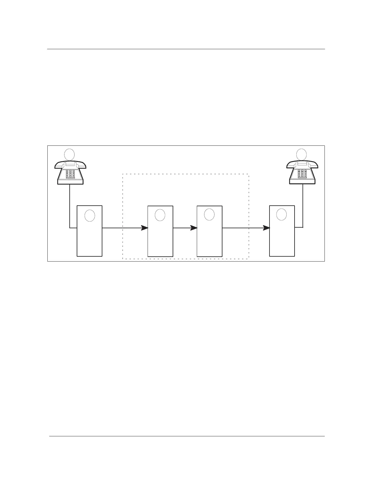
Figure 5-1 shows a call traveling from nodes 1 through 6 as it proceeds
through the various nodes by means of PRI. At node 3 (call incoming on a
PRI) is an originating exchange. At node 4 (call outgoing on a PRI) is a
terminating exchange (the call terminates out of the switch). The user and
network functions are also shown.
Figure 5-1
Originating and terminating exchanges, network and user functions
PBX
DMS-250
3
4
IMT
1
25
Basic
PRI
PRI
User Network
UserNetwork
Originating
user
Originating
exchange
user
Terminating
PBX
DMS-250
ISUP
switch
switch
6
(call originates
into switch)
Terminating
exchange
(call terminates
out of switch)
rate
interface
Basic
rate
interface
MCI
MCI
Network
The various states (or status) of a call (communicated by signaling
messages) are perceived by the network, the user, or both. Unless
specifically qualified, all call states are considered common. The differences
between the functionality of a user and network are as follows:
• Response
— User—When a Q.931 SETUP message is sent by the user side of the
interface, it expects a Q.931 CALL PROC message in response.
— Network—The network side of the interface may receive a CALL
PROC, ALERT, or CONN message in response.
• CONN_SENT—user side
The user interface has one extra Q.931 call state, CONN_SENT.
CONN_SENT is entered when a CONN message is sent to the network.
Timer T313 is started on the user side and is cancelled on receipt of a
Q.931 CONN ACK message. The active state is then entered. When a
network interface transfers a Q.931 CONN message, the network state is
set directly to active (no timer is started).
 Loading...