Call control procedures 5-21
Digital Switching Systems DMS-250 ISDN Reference Manual MWC14 (CSP14)
If an answer is detected by the EVS switch, the CONN message is sent to
the EVS ARU. The EVS ARU does not need to wait for the CONN message
to send the FACILITY message to initiate bridging.
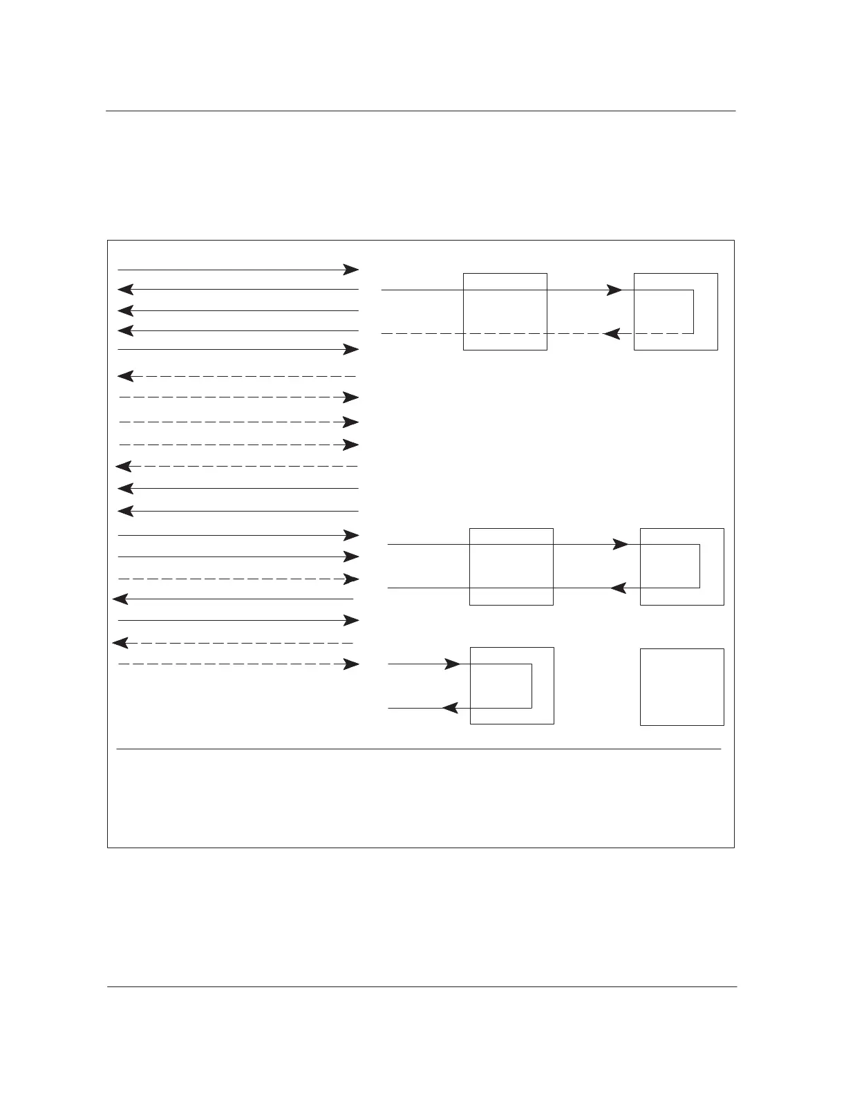
Figure 5-12
Trunk release messaging sequence
1. Leg 1 SETUP
2. CALL PROC
3. ALERT/PROG
4. CONN
5. CONN ACK
EVS switch EVS ARU
PRI
Incoming trunk
Outgoing trunk
(Leg 1)
(Leg 2)
6. Leg 2 SETUP (FAC IE, INV 1, RLT)
7. CALL PROC
8. ALERT (FAC IE, RR1, CALLID)/PROGRESS
9. CONN
10. CONN ACK
11. FACILITY (menu digits)
12. FACILITY (FAC IE, INV 2, RLT, CALL ID)
Incoming trunk
Outgoing trunk
EVS switch EVS ARU
PRI
13. FACILITY (FAC IE, RR 2, RLT)
14. DISC
15. DISC
16. REL
17. REL COM
18. REL
19. REL COM
Incoming trunk
Outgoing trunk
EVS switch
EVS ARU
Legend:
FAC IE: EVS service ID (IE = information element)
INV 1: INVOKE component with an ID of 1
RLT: Release link trunk
RR: RETURN RESULT component with the corresponding INVOKE ID of 1
Q.931 SETUP message
The leg 1 SETUP message (as shown in Figure 5-12) includes the OTG and
OSID values in the Generic Digits parameter. The leg 1 SETUP message
also includes the value dialed number identification services in the Generic
Digits information element.





 To Next Page