8-1
Indicators
8
This chapter describes the status indicator lights (LEDs) of the Passport 4400
(4430/4450/4455). The indicators can be seen through a series of small windows
located at the front of the unit.
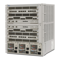
Figure 8-1. Location of Indicators on Passport 4400
The following status indicator lights are explained:
• Ethernet Base Module on page 8-1
• T1/E1 Voice Module on page 8-2
• Digital Voice Channel Status Indicators on page 8-3
• T1 and E1 Status Indicators on page 8-4
• Digital Voice Expansion Module on page 8-6
• Analog Voice Module and Universal Analog Voice Module on page 8-7
• ISDN BRI Voice Module on page 8-8
Ethernet Base Module
The bottom window contains the status indicators for the Ethernet Base Module,
in addition to any serial interface modules that are installed. The functions and
colors of the indicators vary according to the operation of the unit. See
Table 8-1 on page 8-2 for a description of the indicator functions.
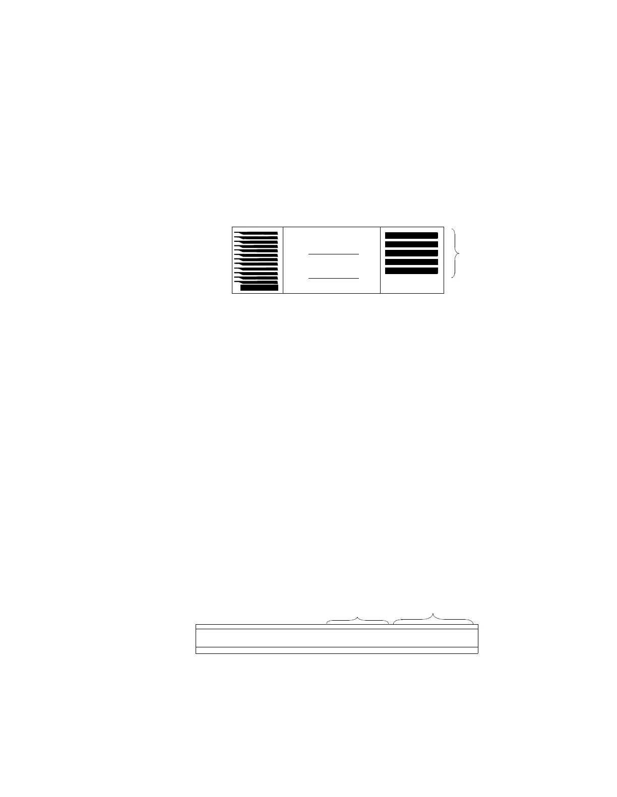
Figure 8-2. Ethernet Base Module Indicators
Indicators
Base Module Indicators
Interface Module
Indicators
P2 P1 F4 F3 CC CPP3
 Loading...