5. Voice Alarm Systems AA-30 Audio Amplifiers
36 AFP-300/AFP-400 Operations PN 50260:C1 05/22/97
AA-30 Audio Amplifiers
Note: For instructions on setting
the Audio Gain Rotary Switch,
refer to “Adjusting the Audio
Gain Level (AA-30, AA-100/AA-
120)” on page 38.
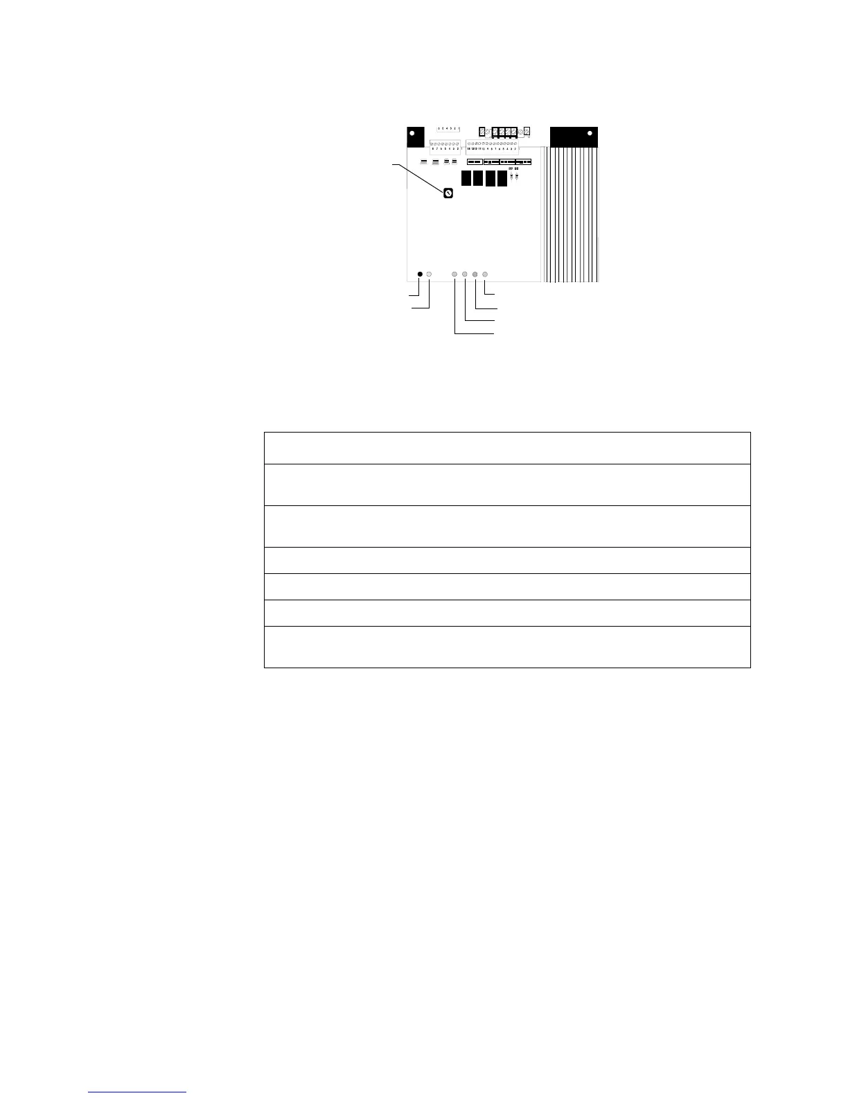
Figure 36 shows the layout of the AA-30 circuit board and identifies AA-30
components:
Figure 36 AA-30 Circuit Board
Table 32 lists the conditions that cause each AA-30 System Status Indicator LED to
light:
Table 32 AA-30 Components
Notes:
1. The amplifier does not indicate a trouble condition until 40 seconds after these
faults occur.
2. To calibrate audio amplifiers, install a 470-ohm resistor at the end of the low-level
audio circuit. If the low-level audio circuit is configured as four wire circuit, install
a 470-ohm resistor at the point furthest from the AMG-1 or ATG-2.
LED Lights when...
Normal Level The audio amplifier is adjusted properly and operating correctly
during normal (non-alarm) conditions.
Incorrect Level The audio amplifier is out of adjustment during normal (non-alarm)
conditions.
Speaker Trouble An open circuit condition occurs in the four-wire, high-level output.
Amplifier Trouble A loss of the low-level audio input signal, or an amplifier failure.
Battery Trouble The battery voltage is below a sufficient level.
Brownout The AC power source is below a sufficient level. During a complete
loss of AC power, no LEDs will light on the AA-30.
Audio Gain Rotary Switch
Normal Level LED
Incorrect Level LED
Speaker Trouble LED
Amplifier Trouble LED
Battery Trouble LED
Brownout LED
Technical Manuals Online! - http://www.tech-man.com