Section 2 System Overview Product Diagram
12 NFS-3030 Installation PN 51330:C 10/28/2003
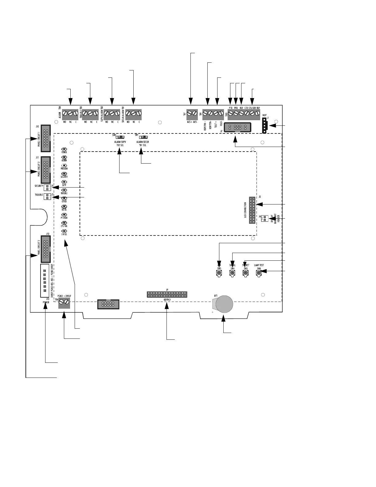
Figure 1 CPU Connections
J4 backlight connection
J2 LCD connection
SW3 Acknowledge
SW4 Signal Silence
SW5 System Reset
SW6 Lamp Test
Lithium battery for backup of
on-board memory (See Section 3.5.1
“Memory-Backup Battery”.)
Test fixture:
No connection
Status Indicator LEDs (See Figure 3)
J9 Keypad connection
Service-level switches
for local operation
without keypad/display
J13 Power connections (non-power-limited)
(See Section 3.15 “Connecting Power Sources and Outputs”)
J6 Security switch connection
J5 Trouble bus connection
SW2 Supervisory
SW1 Security
J7 SLC Loops
(Connect to
first LCM-320)
Cable P/N 75565
J1 Network/Service
Connection (NUP)
Cable P/N 75556
TB4 Alarm Relay
TB3 Trouble Relay
TB2 Supervisory Relay
TB1 Security Relay
J10, J11, J12 Panel circuit module connections
(power-limited, supervised) Cable 71088 (See Figure 12)
Note: Relay circuits are power-limited only if
connected to a power-limited signal source.
Relays are rated for 2A@30Vdc resistive.
Note: Dotted line indicates location of optional keypad & LCD display
TB9 TOUT+/- : Future Use
TB7 ACS (power-limited, supervised)
TB5, CTS/CRX Keltron printer
supervision
(TB5, CTS & REF No connection)
TB5, left side. Printer (isolated)
3030board.cdr
TB6 Accessory Power (See
Section 3.15 “Connecting Power
Sources and Outputs”)
TB9 RDP devices such as LCD-160