Form-C Relays on the CPU Section 3 Installation
NFS-3030 Installation PN 51330:C 10/28/2003 35
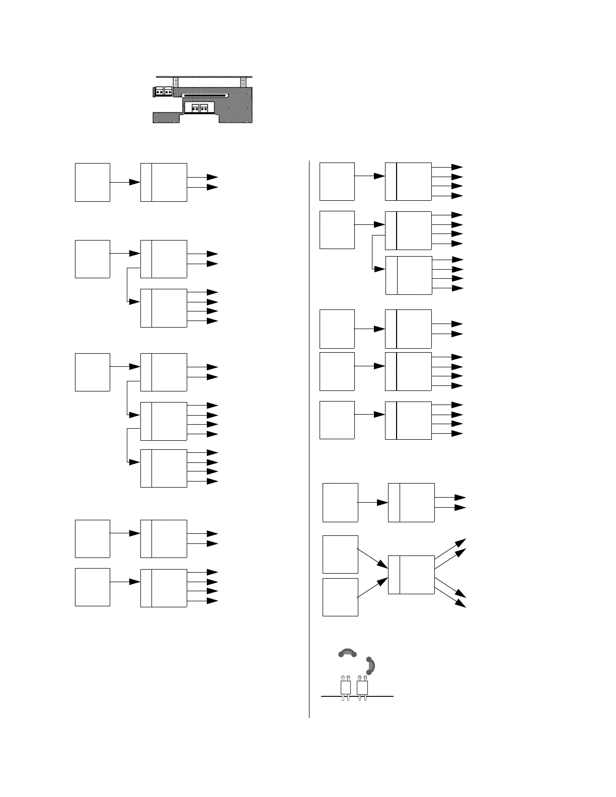
3.13 Notification Appliance Circuit Current Limitations
The total current available from any group of Indication Appliance Circuits
cannot exceed 3.0 amps. Figure 22 illustrates some of the typical power
supply/ Notification Appliance Circuit configurations.
Note: The term “total” in these figures assumes that no Notification
Appliance power is drawn for any other purpose.
Figure 22 Typical Supply/Notification Circuit Configurations
J5 J6
(ICM-4RK)
J5 J6
(ICE-4)
Bottom wire of the
ICM-4RK/ICE-4
These two
Notification
Appliance
Circuits share
the total MPS
current.
Main
Power
Supply
J5
CPU
Module
These six
Notification
Appliance
Circuits share
the total MPS
current.
Main
Power
Supply
J5
J6
CPU
Module
J5
J6
ICM-4RK
These ten
Notification
Appliance
Circuits share
the total MPS
current.
Main
Power
Supply
J5
J6
CPU
Module
J5
J6
ICM-4RK
J5
ICE-4
These two Notification
Appliance Circuits
share the total MPS
current.
Main
Power
Supply
J5
J6
CPU
Module
J5
J6
ICM-4RK
Auxiliary
Power
Supply
These four Notification
Appliance Circuits
share the total current
provided by the
auxiliary power supply
These four Notification
Appliance Circuits
share the total current
provided by the
auxiliary power supply
Auxiliary
Power
Supply
J5
ICM-4RK
J5
J6
ICM-4RK
Auxiliary
Power
Supply
These eight Notification
Appliance Circuits
share the total current
provided by the
auxiliary power supply
J5
ICE-4
These two Notification
Appliance Circuits
share the total MPS
current.
Main
Power
Supply
J5
CPU
Module
These four Notification
Appliance Circuits
share the total current
provided by the
auxiliary power supply
Auxiliary
Power
Supply
J5
ICM-4RK
J5
ICE-4
Auxiliary
Power
Supply
These four Notification
Appliance Circuits
share the total current
provided by the
auxiliary power supply
These two Notification
Appliance Circuits
share the total MPS
current.
Main
Power
Supply
J5
CPU
Module
Auxiliary
Power
Supply
J5
J6
ICM-4RK
Auxiliary
Power
Supply
For this particular configuration (using
two auxiliary power supplies to power
on ICM-4RK or ICE-4), cut jumper JP1
and JP2 located above J5 and J6.
icejump. cdr
JP2
JP1
JP5
JP6
These two Notification
Appliance Circuits
share the total current
provided by the
auxiliary power supply
These two Notification
Appliance Circuits
share the total current
provided by the
auxiliary power supply