ULC Remote Connection Feature Section 3 Installation
NFS-3030 Installation PN 51330:C 10/28/2003 41
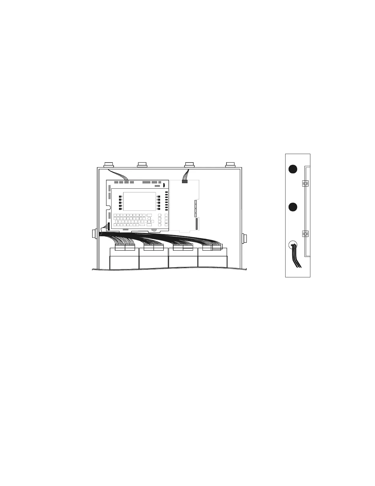
3.16 UL Power-limited Wiring Requirements
Power-limited and non-power-limited circuit wiring must remain separated in the cabinet. All power-
limited circuit wiring must remain at least 0.25 inches (6.35 mm) from any non-power-limited circuit
wiring. All power-limited and non-power-limited circuit wiring must enter and exit the cabinet through
different knockout and or conduits. To maintain separations easily, it is recommended that non-power-
limited modules are grouped together. For example, use a separate row or designated side of the
enclosure so that power-limited and non-power-limited wiring do not cross. Install tie wraps and
adhesive squares to secure the wiring.
For a quick reference to control panel circuits, refer to Figure 1 at the start of this manual. The power-
limiting label inside your cabinet door identifies which compatible modules have power-limited or non-
power-limited wiring.
Figure 29 Typical Wiring in a Four-Row Backbox
Some devices (such as ACM-8R, ARM-4, CRM-4RK, CRE-4, and LDM-R32) are power-limited only
when connected to power-limited sources. When one of these devices is connected to a non-power-
limited source, the power-limited marking must be removed, and at the time of installation, each non-
power-limited circuit connected to these modules must be identified in the space provided on the
cabinet door label.
Note: Relays are power-limited only when connected to power-limited sources for the relay outputs.
3.17 ULC Remote Connection Feature
ULC requires that devices such as TM-4 and UDACT be disconnected during annual testing to prevent
transmission of false alarms.
Disconnecting TM-4 for Annual Testing. Follow standard installation procedures as described in
the TM-4 installation documentation. To disable reporting, slide SW4 Disable All Output switch from
“Enable” to “Disable.” Refer to TM-4 documentation for product drawing.
Disconnecting UDACT for Annual Testing. Install UDACT as the last device on the EIA-485
line, with a listed key switch such as AKS-1B installed on the EIA-485 line. In this case only, install the
ELR between the EIA-485 wires just in advance of the key switch (see Appendix 30 “Wiring a
Keyswitch to Disconnect UDACT During Annual Testing”). The key switch should installed so that
NFS-3030
3030ULWIRING.cdr
Nonpower-limited circuit
(Assumes relay is connected to a
non-power-limited signal source)
Side-View
Separating non-power-limited and
power limited circuits within the
backbox with adhesive squares
amps24cab3wiring.CDR
NFS-3030
LCM-320
or
LEM-320
Power-limited
circuits
Power-limited
circuits