EasyManua.ls Logo

Nova Florida VELA COMPACT - 3.2.3 Positioning the Boiler

Nova Florida VELA COMPACT
36 pages
Print Icon
To Next Page IconTo Next Page
To Previous Page IconTo Previous Page
Loading...
17
pic. 7 - Template
3
.2.3. Positionin
g
the Boiler
E
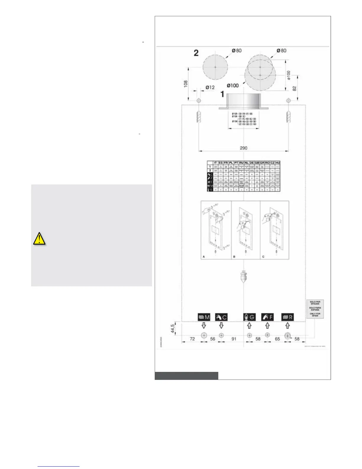
ach unit is supplied alon
g
with a paper template, in
t
he packa
g
e, allowin
g
positionin
g
the pipes connec
-
t
ing
C
H system, DHW system, gas supply, and air
i
ntake/ue
g
as dischar
g
e ducts to the boiler before
i
nstallin
g
the boiler itself.
T
he template is made o
f
highly resistant paper and is
to
be
a
fx
ed
t
o
th
e
w
a
ll
o
n whi
c
h th
e
bo
il
e
r i
s
t
o
be
m
ounted usin
g
a carpenter’s level. It provides all the
i
ndication required in order to drill the holes
f
or
xing
t
he boiler to the wall
,
the boiler is secured to the wall
u
sin
g
two screws and wall plu
g
s.
T
he lower part o
f
the template shows the areas to be
m
arked for the couplin
g
s positionin
g
of boiler con
-
n
ection to the
g
as supply pipe, water mains supply
p
ipe, DHW ow pipe,
C
H ow and return pipes.
T
he u
pp
er
p
art of the tem
p
late shows the areas to
b
e marked for positionin
g
of air intake and ue
g
as
di
sc
h
arge
d
ucts.
S
ince the tem
p
erature of the walls on
whi
c
h
t
h
e
b
o
il
er
i
s mounte
d
an
d
t
h
e
t
em
p
erature of coaxial flue s
y
stem do
n
ot exceed 60°C
,
minimum distances
f
rom
amma
bl
e wa
ll
s
d
o not nee
d
to
b
e
a
rran
g
ed.
F
o
r boilers with s
p
lit
p
i
p
e flue s
y
stem, in
p
resence o
f
amma
bl
e wa
ll
s an
d
p
assa
g
es throu
g
h such walls, provide
i
nsulatin
g
layer between wall and
ue p
i
pes.

Table of Contents

Related product manuals