as supply pipe must be equal or
reater than the boiler one. Cross-section size depends on its len
ore to be sized accordingly.
omply with installation standards enforced in the installation country. They are considered as an inte
ral part of this booklet.
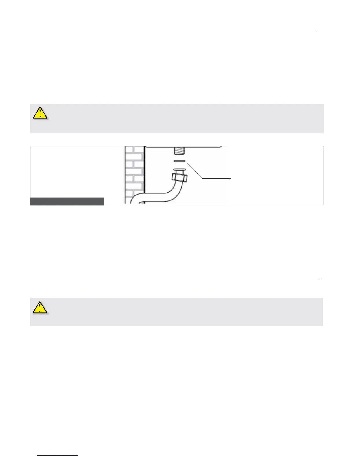
emember that before operate an internal
as distribution system and before connectin
it to a meter, it must be checked for leaks.
orm a leak test, operate according to the
The leak test is to be carried out before the pipes are covered. The leak test must not be carried out usin
as is in the pipes, leak test by a naked ame is forbidden. Use specic products available on the market.
as supply network the use of an appropriately sized and made
uration is not suitable for hemp, plastic tape or similarly made
the boiler, the hydraulic system should be cleaned in order to remove impurities; they mi
e the pump or the heat exchan
e must be connected to their relevant
on the boiler (see pic. 7).
H system pipes, bear in mind load losses caused by radiators, thermostatic valves, radiator gate valves, and the
uration of the system itself.
t is advisable to convey the discharge flow of boiler safety valve to the sewer system.
hould that not be performed, and the
afety valve be activated, floodin
of the room in which the boiler is installed may occur.
he manufacturer shall not be held responsible for any dama
HW ow pipe and water mains pipe must be connected to their relevant 1
ardness of water supplied to the boiler may increase heat exchan
and /or replacement frequency.
on hardness level of the water supplied, it mi
ht be necessary installin
a suitable water treatment device for
licable laws and standards.
marketed water softeners, due to PH level induced in water, ma
Pic. 17 – Gas main connection