H and DHW pipe systems, clean the pipes carefully and eliminate
rease that may be left and that could dama
it reaches the boiler.
Do not use solvents as they could dama
xclusively employ original and manufacturer supplied, air intake/flue gas discharge systems in order to ensure correct
n following the above mentioned information.
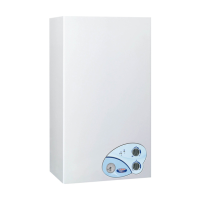
n order to install the boiler,
fx the template to the wall;
heck that 1 cm to the right and 1 cm to the left of the boiler is left for casing removal;
mm Ø holes in the wall for the boiler wall plu
s provided with the boiler and place in the screws;
hen necessary provide holes in the wall to allow air intake and
or ue gas discharge pipes to pass through it;
, the cold domestic water supply pipe
, the domestic cold water ow
ipe (C), and the central heating ow (M) and return pipes (R), as shown on the template (lower area);
onnect the boiler to the feed pipes;
onnect the boiler to the air intake and ue gas discharge system
and ambient thermostat (when available).
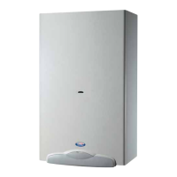
TN boiler model has an open combustion chamber and is desi
or connection to a chimney: combustion air
s drawn directly from the room where the boiler is installed.
c recommendations do not need to be applied involving air intake ventilation openings, or concerning boiler room
rements.
The Manufacturer shall not be held liable for damage resulting in incorrect installation, use, modification of the
n terms of the ue dischar
e into the atmosphere, comply with applicable laws and prescriptions in the country
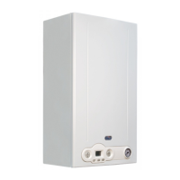
he boiler is equipped with a safety device which is oversees flue gas exhaustion.
n case of malfunction of the air intake
e system, the device shuts down the equipment and no. 1
hould the boiler repeatedly shut down, it is necessary to have the boiler air intake/flue gas discharge ducts checked,
hey could be obstructed or incorrectly sized for flue
as exhaust into the atmosphere.
he chimney is indispensable for correct boiler operation; it must therefore comply with the following requirements:
material and be resistant to
as temperature and related condensate;
it must be as vertical as possible and the roof terminal is to have a removable cap for inspection and cleanin
the chimney diameter is not to be less wide than the boiler ue gas outlet diameter; squared or rectangular section chimneys must
ear an internal section, 10
er than the section connected to the boiler anti-wind
starting from the boiler, the duct connecting to the chimney is to follow a vertical direction and must be long not less than twice its