EasyManua.ls Logo

Nova Florida VELA COMPACT - Air Intake and Flue Gas Discharge System Via 80;80 MM Split Pipes; Pic. 12 - Air Intake and Flue Gas Discharge Split Pipe System (CTFS); Pic. 13 - Dimensions for Connection to Air Intake and Flue Gas Discharge Split Pipe System (CTFS)

Nova Florida VELA COMPACT
36 pages
Print Icon
To Next Page IconTo Next Page
To Previous Page IconTo Previous Page
Loading...
22
Pipe len
g
th (m
)
A
ir intake diaphra
g
m diameter (mm)
0
,5 ≤
L
≤ 10
*
Ø
4
7
10
L
2
6*
N
o
di
ap
h
ra
g
m
* th
e
r
s
t
e
l
bo
w fr
o
m th
e
bo
il
e
r i
s
n
o
t t
o
be
accou
nt
ed
f
o
r
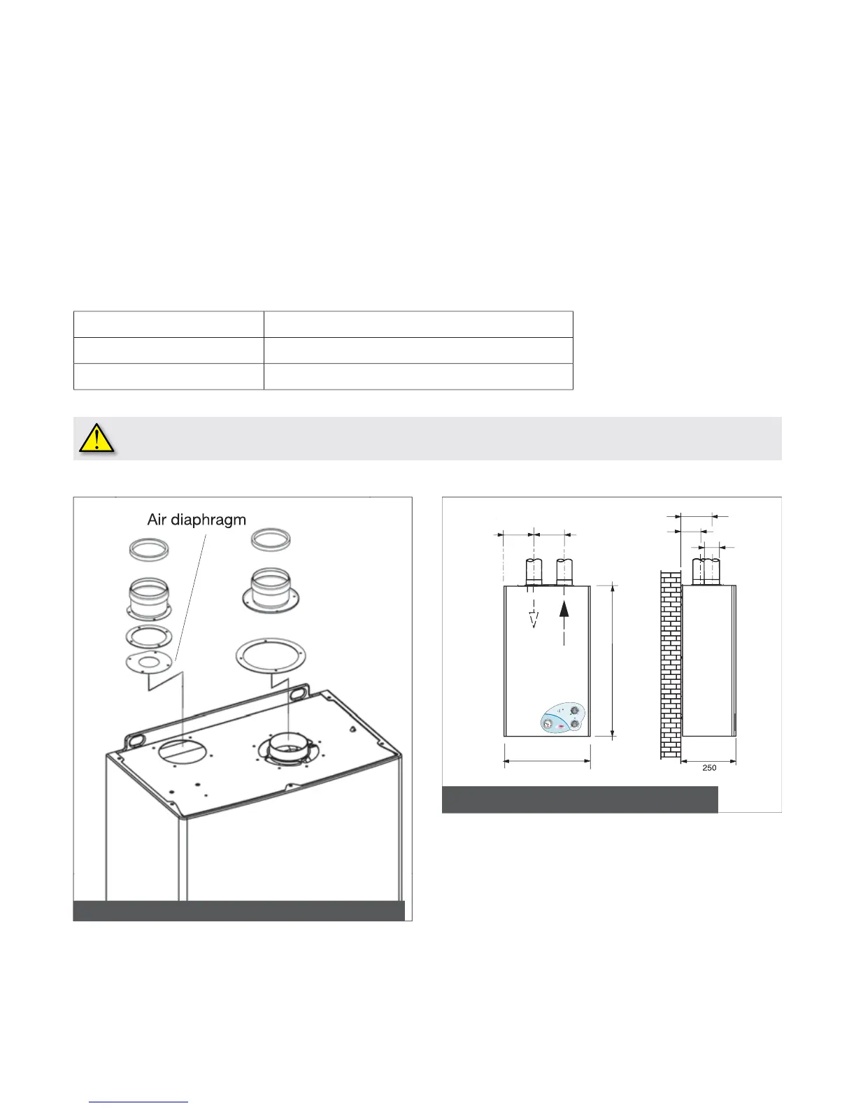
3.2.6.2.3 Air intake and flue
g
as dischar
g
e system via 80/80 mm split pipes
C42 – C52 – C82 installation cate
g
ory
Ai
r
i
nta
ke
Minimum permissible len
g
th of air intake pipe is 1 meter.
Each wide radius 90° elbow (R=D) equals a 1 meter lon
g
pipe section.
Each narrow radius 90° elbow
(
R<D
)
equals a 1 meter long pipe section.
F
lue
g
as dischar
g
e
Minimum permissible length o
f
ue gas discharge pipe is 0,5 meter.
Each wide radius 90° elbow (R=D) in ue
g
as dischar
g
e equals a 1,5 meter lon
g
pipe section.
Each narrow radius 90° elbow (R<D) in ue
g
as dischar
g
e equals a
3
,5 meter lon
g
pipe section.
Choosin
g
the applicable diaphra
g
m supplied with the boiler
Ø
4
7 diaphragm is supplied by the manufacturer in the optional air
/
ue gas split pipe kit
The above data are referred to air intake/flue
g
as exhaust systems which are implemented by means of smooth, ri
g
id
manu
f
acturer approve
d
an
d
supp
li
e
d
p
i
pes
.
400
700
1
36,
5
5
6,5
Ø
80
1
1
Pic. 13 - Dimensions for connection to the air intake/flue gas
exhaust split pipe system (CTFS)
Pic. 12 - Air intake/flue gas exhaust split pipe system (CTFS)
108
108
,5
145
145

Table of Contents

Related product manuals