V-50Hz electric power suppl
neutral polarity sequence when power connecting the boiler.
nstallation standards must be complied with and they are considered as an inte
ral part of this booklet.
accessible two-poled switch, with a minimum
mm distance between contacts
is to be installed outside of the boiler. The
witch is to allow power supply cut-o
orm maintenance and service procedures.
ower supply to the boiler must be tted with a differential ma
netic-thermal automatic switch of suitable disconnection capacity.
ed technician to thoroughly check the power network.
he manufacturer shall not be held responsible for any dama
H system pipes are not suitable for grounding power networks.
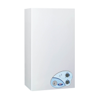
.2.11. Room thermostat connection
he boiler is designed to be connected to an ambient thermostat
not supplied with the boiler
oom thermostat contacts must be properl
sized in compliance with a load of 5 mA load at
must be connected to the relevant terminal board (see electric layout), after removin
he ambient thermostat wirings are N
T to be grouped together with power mains supply cables.
nce all boiler connections have been completed,
he procedure is to be cautiously carried out, followin
valves on all radiators and verify the boiler automatic valve operation;
gradually open the relevant loading tap
, checking all automatic air purging valves installed in the system properly work;
ves as soon as water starts com
check boiler water pressure
tap and bleed any air out a
start the boiler and bring the system to working temperature, stop the boiler and wait
or the pump to stop, then repeat the air blee
stem to cool and restore water pressure to 1 / 1.
y consumption, thereby inte
current local laws and standards it is advisable to use specific products that are
he safety low water pressure switch will not
ive electric consensus to the burner turn on procedure when water pressure
s below 0,4/0,6 bar. CH water pressure is not to be less than 0,8/1 bar. Restore proper value as needed, via the loadin
rovided as standard with the boiler
rocedure is to be followed while the s
auge fitted on the boiler control panel indicates the pressure in the
inactivity of the boiler has its pump may be stuck. Before startin
up the boiler, make sure that the pump is operati
ut a screwdriver into the hole and manuall
operation is completed, screw the protective cap back on and check for water leaks.