installation manual page 31
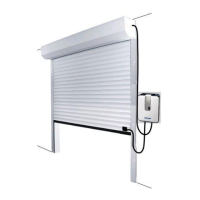
30044.0801.E.01 fast action roller doors
○○○○○○○○○○○○○○○○○○○○○○○○○○○
2.0 assembly step by step
Preliminary remarks :
-do not drag the roller over the ground
-place the roller on a clean surface
-do not step on the screen!
-all points designated with must be lubricated prior to assembly
-the instructions below refer to standard models
2.1 Assembly of the wall guide
1inscribe on both uprights at ca. 1 metre marks absolutely horizontal relative to one another, using where
necessary a water hose (see fig. 2.1.1).
2 check on the basis of these two marks whether the floor in the vicinity of the assembly surface is even (see
fig. 2.1.2).
3place the wall guide (profile fitted with slotted holes) against the uprights using screw clamps (see fig. 2.1.3)
at equal heights and vertically (when the distance between mark and floor does not exceed 15 mm the wall
guides may be placed on the floor).
Always measure the external dimension of the wall guide:
for Speed Roller B + 216
for Speed Roller Heavy B + 440
B = clear width on the order form. Caution! This may differ from the true clear width!
4 secure the wall guide with bolts to the uprights.
5remove the screw clamps and check once more precisely the position of both wall guides.
6 fit the carriage bolts (prior to the assembly of the consoles and the attachment profile of the drive) with O-
rings in the consoles (see fig. 2.1.4) .
7 fit the consoles to the wall guide with one bolt in the uppermost slotted hole (this slotted hole corresponds
with the uppermost slotted hole of the wall guide).
8 check with a spirit level whether both consoles are level relative to one another.
9 secure the console with the remaining bolt connections.
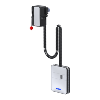
2.2 Assembly of the upper roller and drive
1place the filler block and flange bearing on both sides of the roller on the spindle (see fig. 2.2.1).
2place the key in the keyway and slide the drive on the spindle
3raise the roller with a forklift truck and secure the flange bearings with the carriage bolts fitted earlier (see
point 6 of 2.1), washers and self-locking nuts (the O-rings may remain in position).
4 check accurately whether the roller is level.
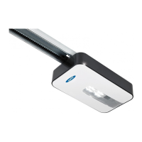
5 fit the attachment profile of the drive to the console with the carriage bolts fitted earlier (see point 6 of 2.1),
washers and self-locking nuts (the O-rings may remain in position).
7 check whether the drive is suspended vertically.
2.3 Assembly of the lower beam