installation manual page 33
30044.0801.E.01 fast action roller doors
1remove the binding from the roller.
2insert the crank into the drive (see fig. 2.3.1), uncouple the engine brake and manually lower the doorplate
completely.
3withdraw the doorplate fully from the guide.
4slide the lower beam over the reception profile of the doorplate and divide it so that the distance between wall
guide and lower beam is the same on both sides (fig. 2.3.2). Do not yet secure doorplate and lower beam!
5close and open the door at least 10 times (manually or after electrical connection with the push buttons of the
dead man’s handle).
6 check once more whether the lower beam is properly centred relative to the wall guide. When this is the case,
secure the doorplate to both sides of the lower beam:
-for speedroller Economic or Speedroller Polara with M6 flange headed screws (see fig. 2.3.3)
-for Speedroller or speedroller Heavy with M8 flange headed screws (see fig. 2.3.4).
Make sure that the doorplate is tautly secured!
2.4 Assembly of the tension system (when appropriate): see fig. 2.4.1
1allow the doorplate to rise until the entire clear opening is free.
2 unwind the elastic cord completely free from the aluminium disc and then wind it one coil on the aluminium
disc.
3 secure the clamp (with return pulley) in the console with four M8 bolts.
4run the elastic cord through behind the return pulley and pull it down onto the lower return pulley.
5 pull the elastic cord until the loose end of it rests without tension on the attachment point on the lower beam
and then place clamping tongs immediately in front of the lower return pulley.
6 secure the eye of the elastic cord to the wall side of the end piece with an M8 bolt + washer + self-locking nut.
Caution! The eye of the elastic cord must be able to still rotate freely. Repeat this procedure for the other
side.
7remove the clamping tongs and allow the elastic cord to gradually become tense.
8 hook the cover guide to the wall guide and secure it with a flat screw at ca. 400 mm above the floor surface.
9 fit the covers with two M8 bolts.
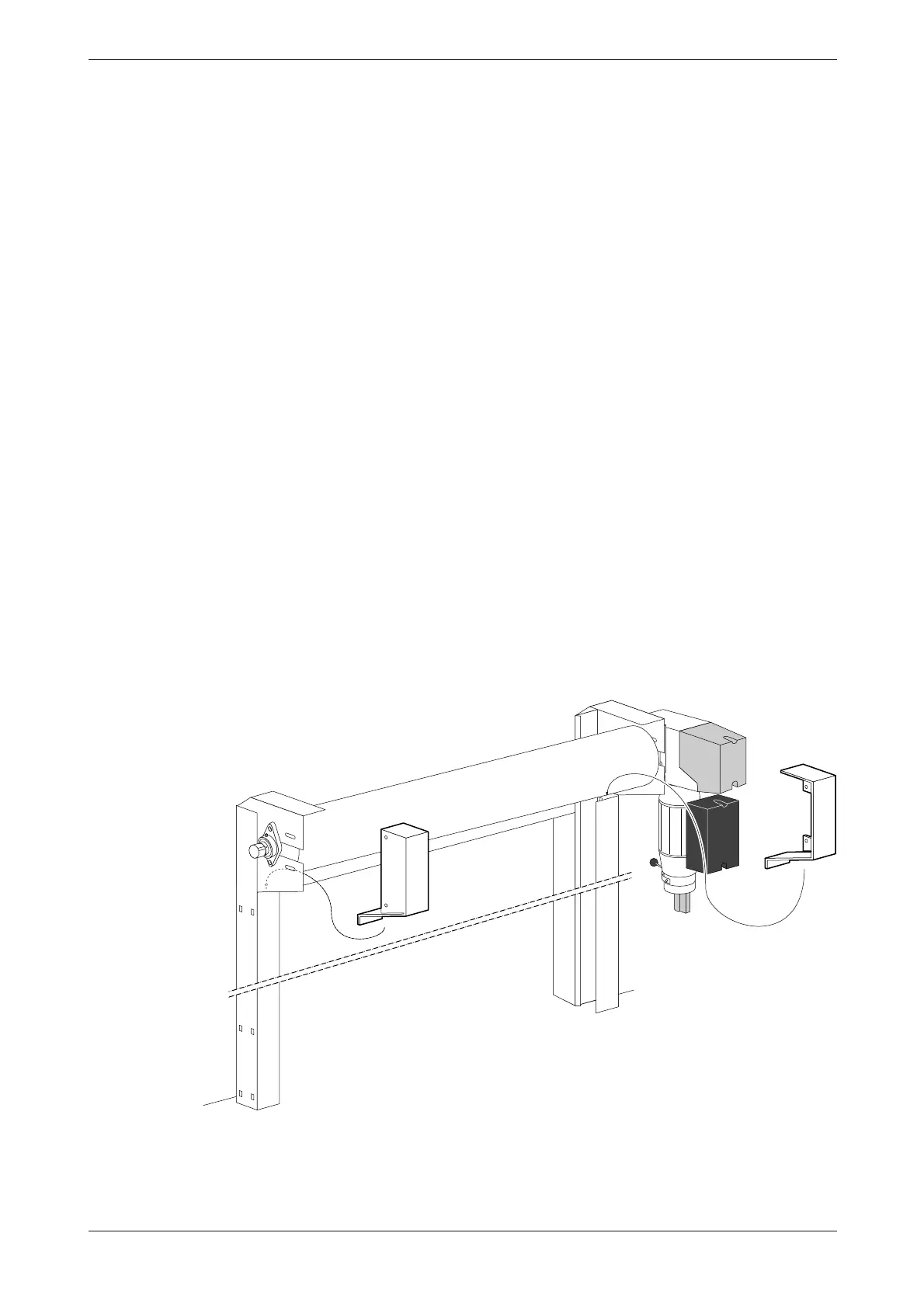
2.5 Fit safety photocell
figure 2.4.2