page 34 installation manual
30044.0801.E.01 technical alterations reserved
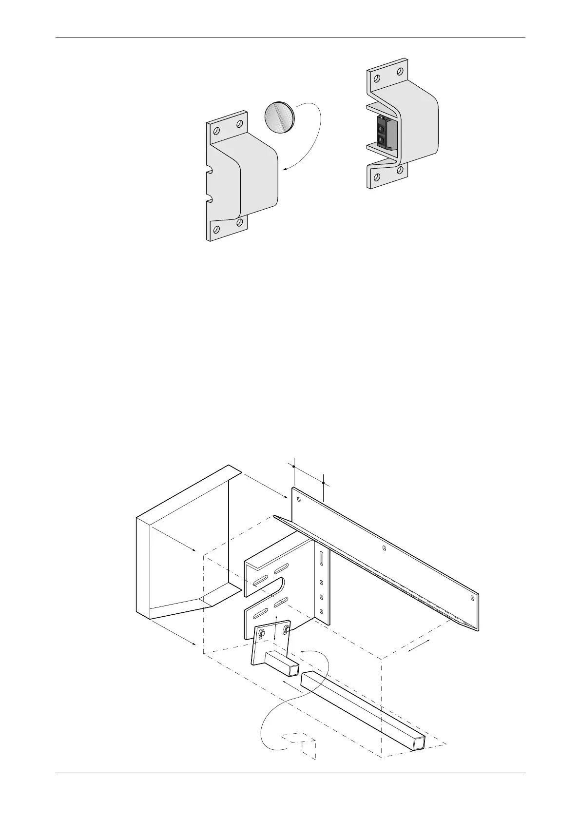
1 fit the safety photocell and reflector (see fig. 2.5.1).
2.6 Assembly junction box for the supply side protection
figure 2.5.1
1 secure the junction box for the spiral cable of the supply side protection on the cover guide (the assembly
holes are pre-drilled).
2.7 Assembly of the protective cover over roller and/or drive
1place the reception profile on the consoles and secure it on the assembly surface above the console (see fig.
2.7.1).
2slide the galvanized sleeve over the tube with assembly plate and secure it complete to the consoles with two
M8 bolts (turn hand-tight).
3place the protective cover on the reception profile and then determine whether the tube is properly located
(where necessary slide the tube until the protective cover is adjacent to it).
4 tighten the M8 bolts.
5place the cover on the drive.
6place the endcap in the hood and attach with the screws delivered.
NB!! The mechanical section of the assembly is now complete. Refer for the assembly of the control
70
figure 2.7.1