30
ROTARY JOINT MAINTENANCE
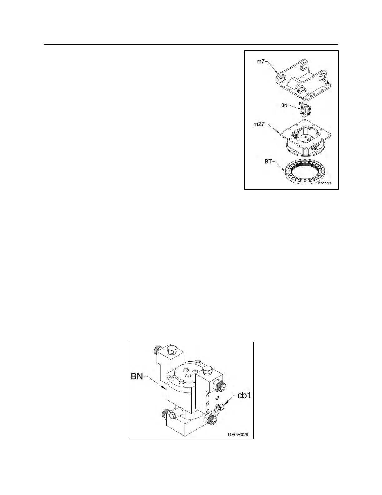
HYDRAULIC ROTARY JOINT
ASSEMBLY
The hydraulic rotary joint assembly (BN) is mounted inside
the swivel top assembly (m27) which is under the top
bracket (m7) that pins to the carrier and is bolted to the
slewing ring (BT) which rotates the Demolition Grab’s
main frame. Hydraulic oil for both open and close
operations passes through it. The rotary joint assembly
consists of two main parts, the “Spindle Case”, which
contains the oil seals and the “Spindle”, which rotates the
Demolition Grab’s main frame.
LEAKAGE OF THE SEALS
External leakage or internal (bypassing) of hydraulic oil
will require the replacement of the seals in the rotary joint
assembly. For external leakage, please review the seal replacement procedure in the
next section. If internal leakage is suspected, please proceed to the “TESTING THE
ROTARY JOINT SEALS FOR INTERNAL LEAKAGE” section.
TESTING THE ROTARY JOINT SEALS FOR INTERNAL
LEAKAGE
If internal seal leakage is suspected, before disassembling the rotary joint assembly
(BN), the counterbalance valve cartridge (cb1) pressure setting should be checked.
Internal leakage will most likely prevent the unit from reaching relief pressure in the
close function. The relief cartridge is located below the rotary joint in a block that the
hose connections to the cylinder are located. Access to the relief valve cartridge is
through the cover plates of the swivel top assembly.
NOTE: Before attempting to adjust the relief setting, please check that the relief valve
cartridge has not loosened in the block.