37
TROUBLESHOOTING
RELIEF VALVE CHECKING AND SETTING PROCEDURE
B. DEMO GRAB’S COUNTERBALANCE VALVE
After the carrier’s hydraulic circuit has been verified, check the Demo Grab’s
counterbalance valve setting.
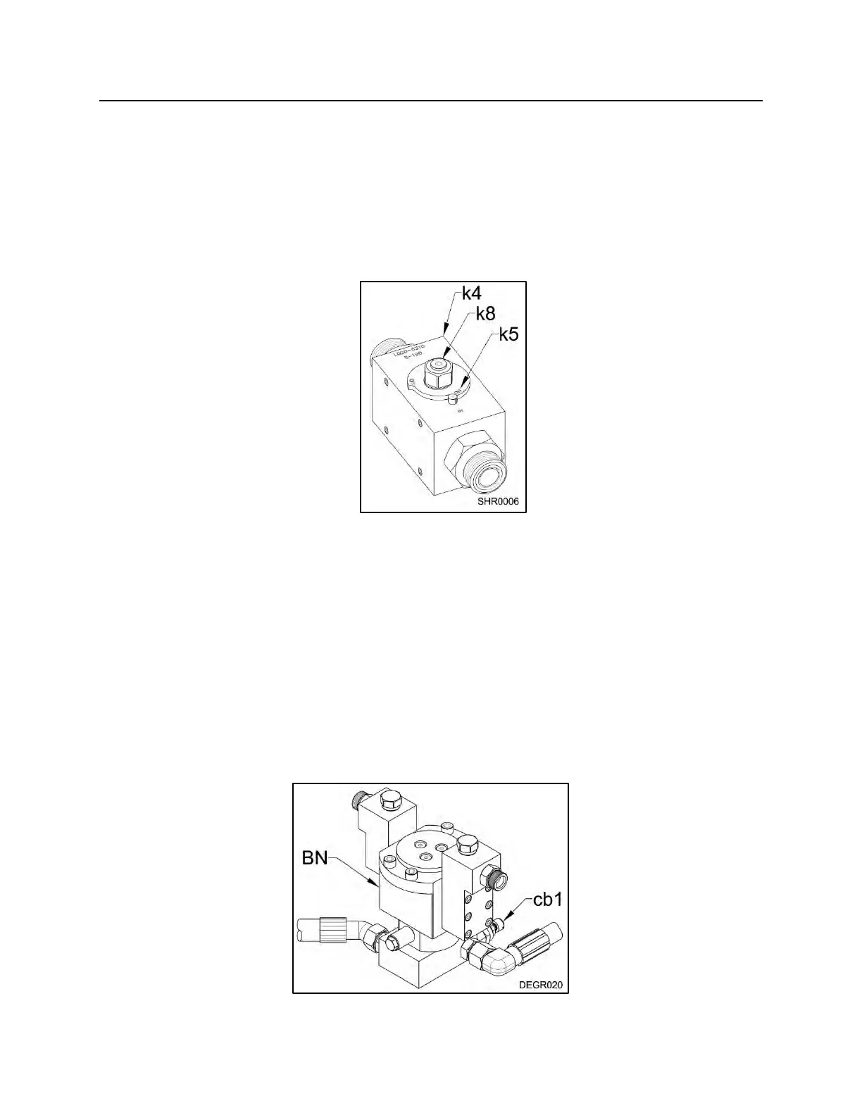
1. With the 0 – 5,000 psi (0 – 350 bar) gauge in the arm close side and the 0 –
5,000 psi (0 - 350 bar) in the arm open side of the stick, turn the shut-off valves
(k4) to the “ON” position (k5).
2. Start the carrier. Set the throttle to the full position then close the arms
completely and hold for ten seconds. Check the psi (bar) reading on the gauge
and compare to the Demo Grab’s specified counterbalance valve setting. If the
reading is not per specification, see “SPECIFICATIONS”, pages 9 through 12
and reset the counterbalance valve cartridge. If you are unable to reset the
counterbalance, refer to the troubleshooting chart.
COUNTERBALANCE VALVE LOCATION
The counterbalance valve cartridge (cb1) is located in the manifold block, which is part
of the rotary joint assembly (BN). (See the unit’s parts breakdown for the location of the
rotary joint.)