35
TROUBLESHOOTING
DETERMINE THE TYPE OF PROBLEM
Performance problems are classified as “LOSS OF POWER” OR “LOSS OF CYCLE
SPEED” (assuming the problem is not due to misapplication).
1. LOSS OF POWER
NPK attachment grabbing forces are determined by the operating pressure
settings.
2. LOSS OF CYCLE SPEED
NPK attachment cycle speed is determined by the hydraulic flow to the unit. The
hydraulic installation circuit must be set to provide the correct oil flow.
DETERMINE THE CAUSE OF THE PROBLEM
Technical problems are caused by either the NPK attachment or the hydraulic circuit
(carrier hydraulics or installation kit). Checking the hydraulic pressure and flow will
determine if the problem is in the Demo Grab or the carrier. If the pressures and flow
available to the Demo Grab are correct, the problem is in the Demo Grab.
GUIDE FOR LOSS OF POWER (relief valve checks)
Loss of power can be caused by a low carrier relief valve setting or a low Demo Grab
relief setting. Verify the correct relief valve settings of the carrier and the Demo Grab.
Refer to the “RELIEF VALVE CHECKING AND SETTING PROCEDURE” and the
troubleshooting chart.
MEASURING OPERATING PRESSURES
Tools and Equipment required:
Qty. 1 -Pressure gauge: 0 – 5,000 psi (0 – 350 bar), for arm close circuit.
Qty. 1 -Test port adapter: to fit #4 SAE female port in the NPK shut-off valve.
Qty. 1 -Test hose: rated for 5,000 psi (350 bar).
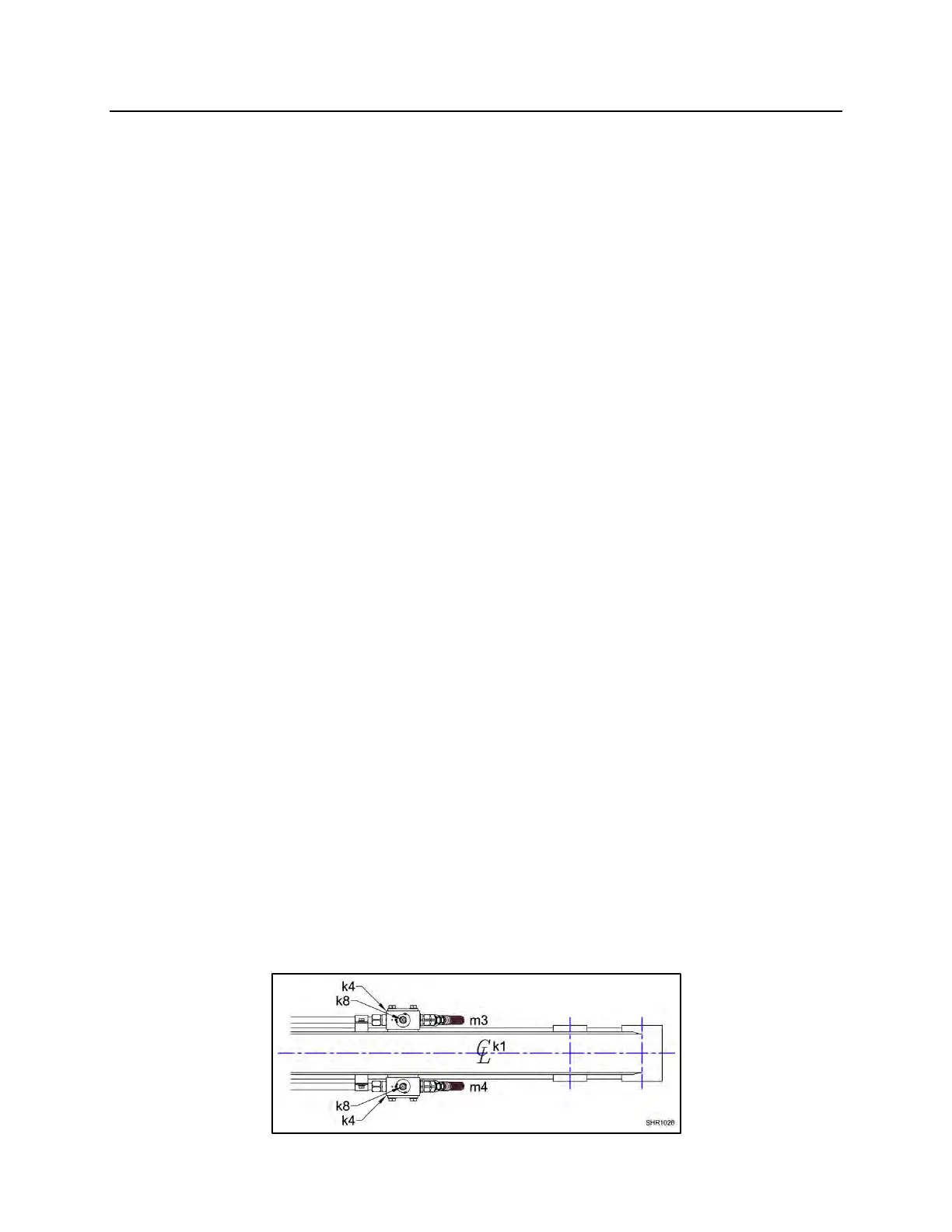
RELIEF VALVE CHECKING AND SETTING PROCEDURE
NPK Installation Kits provide shut-off valves (k4) with test ports (k8) in both arm open
(m4) and arm close (m3) hydraulic lines. Install pressure test hoses in both the arm
open and arm close test ports.