39
TROUBLESHOOTING
TROUBLESHOOTING FOR SLOW CYLINDER SPEED
The cycle times of the Demo Grab are controlled by the flow provided by the hydraulic
circuit of the carrier. The cycle times of the Demo Grab are a direct result of the
maximum published oil flow, see “SPECIFICATIONS”, pages 9 through 12.
NOTE: If the jaws will not open or close, be sure the right and left shut-off valves are
open.
CHECKING HYDRAULIC FLOW AT RATED PRESSURE
Tools and Equipment required:
Qty. 1 -Pressure gauge: 0 – 5,000 psi (0 – 350 bar), for arm close circuit.
Qty. 1 -Test port adapter: to fit #4 SAE female port in the NPK shut-off valve.
Qty. 1 -Test hose: rated for 5,000 psi (350 bar).
Qty. 1 -Hydraulic flow meter: pressure loading type, 0 – 100 gpm (0 – 380 lpm)
minimum capacity.
PROCEDURE FOR CHECKING HYDRAULIC FLOW AT RATED
PRESSURE
1. Install a pressure gauge in the shut-off valve of the close side (left) of the
hydraulic circuit.
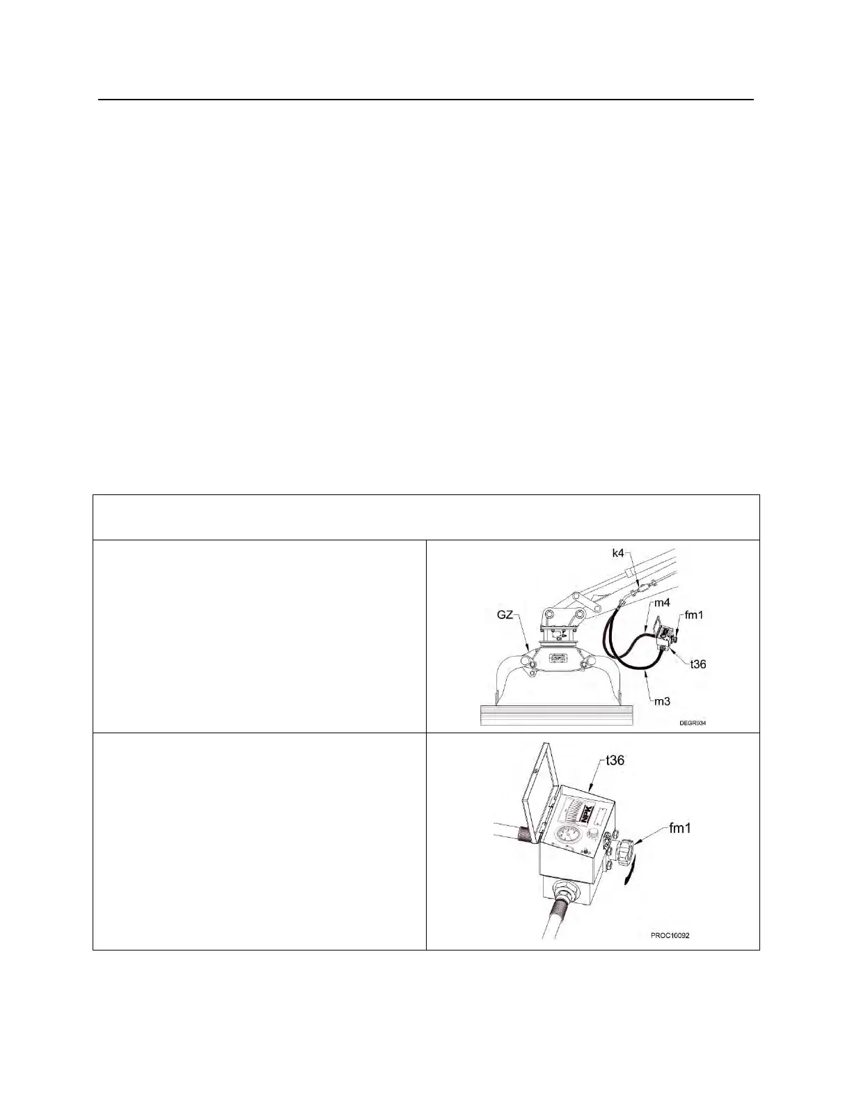
2. Install; a flow meter (t36) between
the Demo Grab (GZ) close and
open lines as shown.
NOTE: Typically, the arm close line
(m3) is on the left (from the
operator’s) seat and arm open (m4)
is on the right.
3. To determine return line pressure
(pressure drop) open both shut-off
valves (k4) and energize the arm
close circuit. Measure the pressure
with the load valve (fm1) of the flow
meter in the full open position.