40
TROUBLESHOOTING
PROCEDURE FOR CHECKING HYDRAULIC FLOW AT RATED
PRESSURE
4. To determine the available flow and relief valve setting of the carrier, follow the
following procedure.
a. Adjust the load valve on the flow meter to zero restriction. Start the
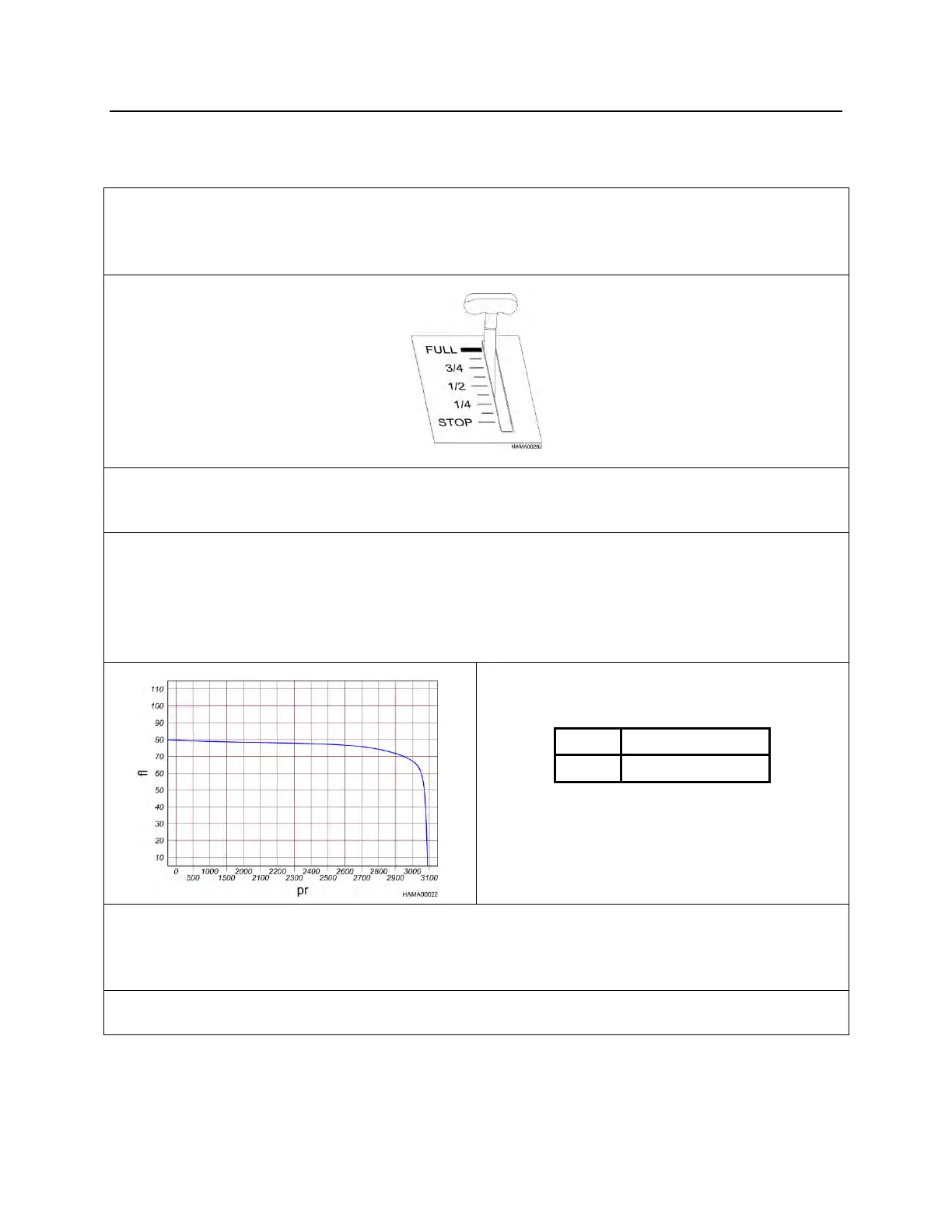
carrier. Set the throttle to the “FULL” position.
b. Energize the close hydraulic circuit. Adjust the flow meter load valve until
the system reaches about 1,000 psi (70 bar). Warm the hydraulic system
of the carrier to normal operating temperature.
c. With the engine at full throttle and the flow meter set at zero pressure,
energize the close circuit. Turn in the loading valve adjustment knob and
record pressure and flow at regular intervals on graph paper. Record
pressure on one axis of the graph and flow on the other. Increase
pressure until the relief valve setting of the carrier is reached. This is the
circuit flow chart.
d. Then set the flow meter at 1,000 psi (70 bar) and check flow. See
“SPECIFICATIONS” pages 9 through 12, for the correct flow for your
Demo Grab. If the reading on the flow meter does not match the Demo
Grab specification, adjust the flow of the carrier.
e. If the cycle speed is still too slow, refer to the slow cylinder speed
troubleshooting chart on the next page.