36
TROUBLESHOOTING
RELIEF VALVE CHECKING AND SETTING PROCEDURE
A. THE CARRIER’S HYDRAULIC CIRCUIT RELIEF VALVE
Verify that the hydraulic circuit meets the Demo Grab’s (GZ) requirements; see
“SPECIFICATIONS”, pages 9 through 12.
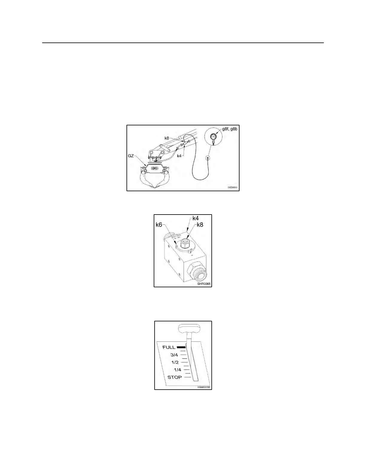
1. Install a 0 – 5,000 psi (0 – 350 bar) pressure gauge (g8f) in the #4 SAE test port
(k8) on the arm close side and a 0 – 5,000 psi (0 – 350 bar) pressure gauge
(g8b) in the #4 SAE test port on the arm open side located in both shut off valves
(k4) at the end of the stick.
2. Turn the shut-off valves (k4) to the “OFF” position (k6).
3. Start the carrier. Set the throttle to the “FULL” position. Actuate the hydraulic
circuit to close the Demo Grab’s arms.
4. The pressure reading on the gauge should be a minimum of 500 psi (34 bar)
above the Demo Grab’s relief valve setting, see “SPECIFICATIONS”, pages 9
through 12. NOTE: If the carrier’s relief is not set at a minimum of 500 psi (34
bar) above the Demo Grab’s relief, reset or replace at this time.