INTRODUCTORY 6. WIRING and CONNECTION
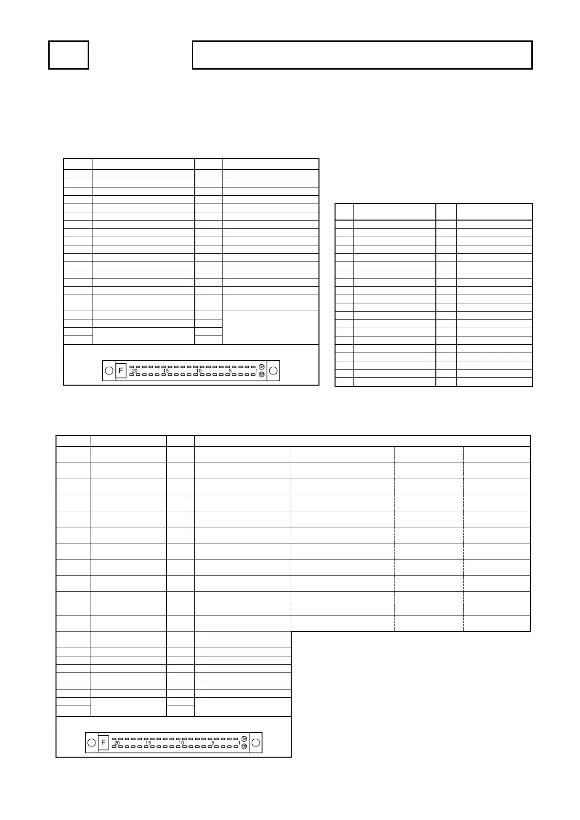
6-3-5. I/O Connector Pin Arrangement
(1) VS-5F, VS-5FD, VS-5F-1, VS-5FD-1
① Switch output connector (SWITCH OUTPUT)
The pin arrangements of switch output connectors are the same both VS-5F(-1) and VS-5FD(-1).
[ Connector model: FCN361J040-AU / FCN-360C040-E (FUJITSU COMPONENT LIMITED) ]
Timing pulse /
Motion detection switch output
Switch output enabling input
0V output common
+24V input common
Shows the pin arrangement as viewed from the soldering terminals side.
② BCD output connector (BCD OUTPUT)
VS-5FD(-1) is equipped with this connector. VS-5F(-1) is not.
[ Connector model: FCN361J040-AU / FCN-360C040-E (FUJITSU COMPONENT LIMITED) ]
Current position value output
(BCD) 0.5
Current position value output
(gray code (720-division)) 2
0
Speed output 1 Speed output 2
Current position value output
(BCD) 1
Current position value output
(gray code (720-division)) 2
1
Speed output 2 Speed output 4
Current position value output
(BCD) 2
Current position value output
(gray code (720-division))2
2
Speed output 4 Speed output 8
Current position value output
(BCD) 4
Current position value output
(gray code (720-division))2
3
Speed output 8 Speed output 16
Current position value output
(BCD) 8
Current position value output
(gray code (720-division))2
4
Speed output 16 Speed output 32
Current position value output
(BCD) 10
Current position value output
(gray code (720-division))2
5
Speed output 32 Speed output 64
Current position value output
(BCD) 20
Current position value output
(gray code (720-division)) 2
6
Speed output 64 Speed output 128
Current position value output
(BCD) 40
Current position value output
(gray code (720-division)) 2
7
Speed output 128 Speed output 256
Current position value output
(BCD) 80
Current position value output
(gray code (720-division))2
8
Speed output 256 Speed output 512
Motion detection switch
Current position value output
(BCD) 100
Current position value output
(gray code (720-division)) 2
9
Speed output 512 Speed output 1024
Current position value output
(BCD) 200
Speed output 1024 Speed output 2048
Current position HOLD
input
Latch pulse output
+24V input common
0V output common
Shows the pin arrangement as viewed from the soldering terminals side.
● External cable (VS-C05)
Indicates external cable wire colors and markings.
It can be used at either the switch output connector
or the BCD connector.
Wire colors & markings
Wire colors & markings
 Loading...