OPERATION 8. HOW TO USE APPLIED FUNCTIONS (PARAMETER)
(1) Edge timing
Designating the reading method by the edge timing is as follows:
- Designates the parameter No. 77(HOLD selection) as “0” in advance.
- The setting of the edge timing and updating cycle should be selected between 0 and 2 by the parameter
No.91 (
Latch pulse cycle).
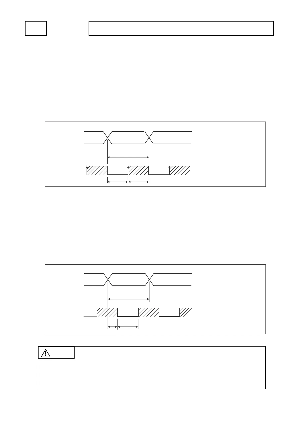
The current position value (speed) output stabilizes at the leading edge of the latch pulse output signal. The
current position value (speed) output should be read at that time.
(2) Level timing
Designating the reading method by the level timing is as follows:
- Designates the parameter No. 77(HOLD selection) as “0” in advance.
- The setting of the level timing and updating cycle should be selected between 3 and 9 by the parameter
No.91 (
Latch pulse cycle).
The current position value (speed) output stabilizes when the latch pulse output signal is ON (LOW level).
The current position value (speed) output should be read at that time.
Data changes Data changes
T2
ON (L)
TS: Latch pulse cycle
Selects by the parameter No. 91.
Setting range
3: 1.406ms,4: 4.219ms,
5: 8.438ms,6: 17.58ms,
7: 35.16ms,8: 70.32ms,
9: 140.6ms
T1 ≒ TS÷4
T2 ≒ TS÷2±0.1ms
OFF (H)
Data changes
Data changes
T1 T2
ON (L)
TS: Latch pulse cycle
Selects by the parameter No. 91.
Setting range
0: 0.352ms
1: 17.58ms
2: 35.16ms
T1 ≒ TS÷2±0.1ms
CAUTION Cautions of the edge timing and level timing
1. The response time lag is approximately 0.1ms when the maximum load current is 10mA.
Design the external circuit with taking the margin for time.
2. The logic of latch pulses is not changed even if the parameter No.78 (BCD output logic) is switched.
 Loading...