1 INTRODUCTION
1.1 Microx Module
The MICROX Module has been designed to allow OEM’S (Original Equipment
Manufacturers) to use the module within their own equipment. Typically, the
DIN and Panel Mount Microx Analyser would be mounted within a control
panel with the sensor connected to the process sample point either within the
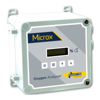
panel or external to the panel. The Wall Mount version is suitable for mounting
in the operational location without further mechanical protection, following a
suitable risk survey being undertaken by the user.
Key design features are:
• Compact enclosure
• Simple keypad calibration facility (utilising onboard LCD display).
• 4-20mA current source output for gas level indication (10-bit
resolution).
• Input voltage range, 24VDC Nominal
or 110-240 VAC. (Panel and Wall mount versions)
• PCB mounted screw terminals for all connections.
• RS232 output for transmission of live data to a PC.
3.1 Operation
When power is first applied to the Microx module an initialisation procedure is
performed as follows:
• All the display segments are displayed
• The software version number is displayed
• The company name is displayed
• The sensor type is displayed
• The display then shows the gas level.
The module is now operational