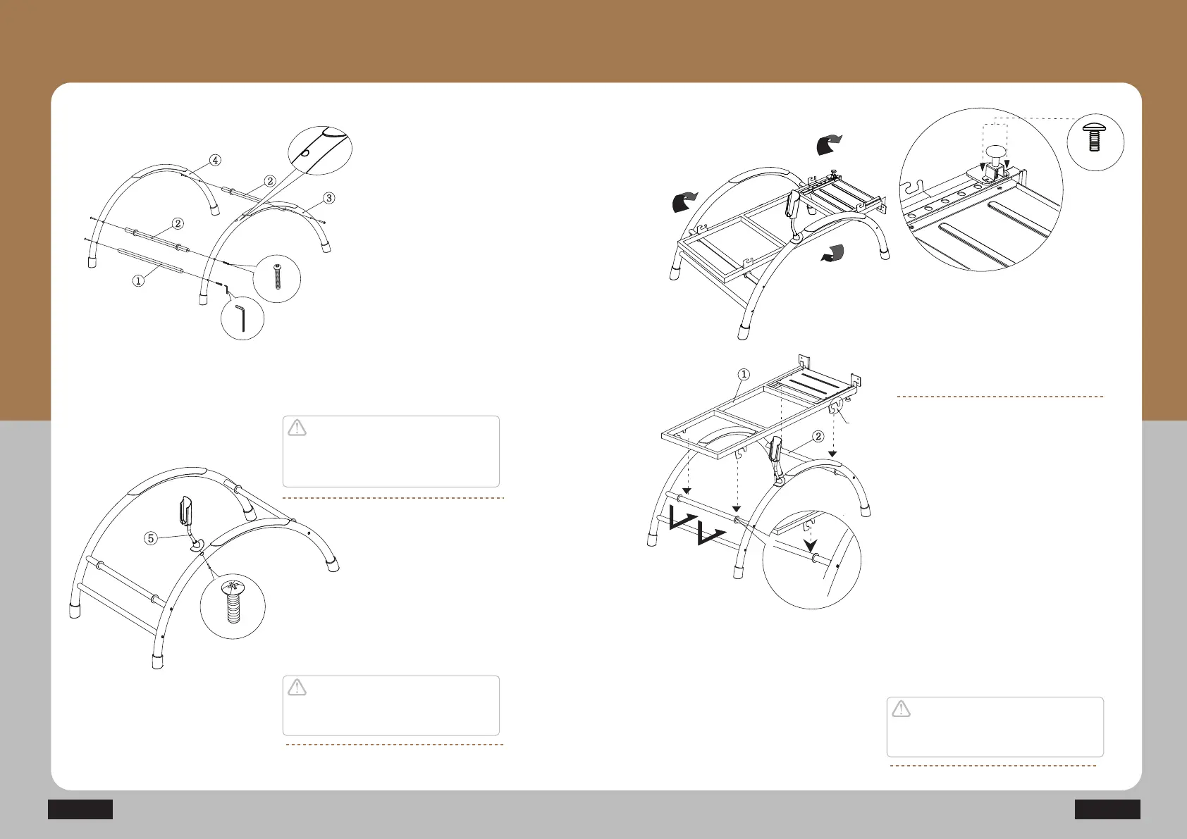
Fixing the controller cover
Placement hole for the
controller cover
Fixing the frame legs
Fixing the main base frame
and the sliding frame
Fixing the Lever
5
2
2
1
3
#
#
4
#
After placing the LEG SUPPORT1 (1) and
LEG SUPPORT2 (2) for the FRAME LEG
ASS'Y-R(3) and FRAME LEG ASS'Y-L(4),
use the fixing screw (B1) to fix in place.
Insert the CONTROLLER HANGER ASS'Y (5)
in the direction indicated in the figure and
fix it with a fixing crew (B2).
Assemble the main base frame (1) in the
direction indicated on the figure and place
the indicated groove area (Q”) on top of
the leg support-2 (2).
Turn the lever in the opposite direction
of the main base frame and place it on
the frame leg. Align it with the hole on the
end of the main base frame and fix it with
a fixing screw (B6).
N4
Insert it
inside the groove.
1
2
2
Production Installation and Use
How to Assemble Product Frame
Caution
Check the assembly direction of the Left
L and Right R parts before fixing the
device.
Caution
Make sure that the screw is placed accurately
into the hole.
Caution
Make sure to insert it in the direction indicated
by the arrow.