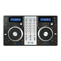
Do you have a question about the Numark MIXDECK EXPRESS BLACK and is the answer not in the manual?
Cycles pitch fader settings (+/- 6%, 12%, 25%, 100%). Can be disabled.
Briefly adjusts music speed faster or slower while button is held.
Returns and pauses music at the last set cue point.
Starts/resumes playback or pauses playback.
Defines loop points or restarts a loop.
Chooses audio source: CD, USB A, USB B, or MIDI controller.
Details RCA and 1/4" TRS jack inputs for microphone and line/phono.
Details RCA and 1/4" TRS jack outputs for master, phone, and aux.
Specifies output level, S/N ratio, frequency response, and distortion.
Steps to remove the unit's outer cabinet and bottom chassis.
Procedure for removing the front PCB and slot-in loader assembly.
Procedure for removing the switching power and main PCB assemblies.
Steps to remove LCM, Mixer, CTRL, and Cross Fader PCB assemblies.
Visual guide of all items included in the product packaging.
Schematic showing electrical connections between internal components.
Exploded view illustrating the physical arrangement of internal parts.
List of all parts, P/N, description, quantity, and reference numbers.
Schematic diagram for the Digital Signal Processor (DSP) module.
Schematic for power supply and input/output interfaces.
Schematic detailing the power regulator for the DSP core.
Schematic for the main input/output circuits.
Schematic diagram for the microcontroller (MICON) unit.
Schematic diagram for the sound card functionality.
Layout of components on the main printed circuit board.
Schematic for the left-side functional PCB.
Schematic diagram for the front panel PCB.
Component layout for the left-side functional PCB.
Schematic diagram for the shielding PCB.
Schematic for the right-side functional PCB.
Layout of components on the right-side functional PCB.
Schematic diagram for the spare PCB.
Schematic for the mixer section, including gain and fader controls.
Schematic and component layout for the servo motor control board.
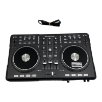
| Type | DJ Controller |
|---|---|
| Decks | 2 |
| Channels | 2 |
| USB | Yes |
| Compatibility | Serato DJ Intro |
| Media | USB, CD |
| Inputs | 2 x RCA |
| Outputs | RCA |
| Microphone Input | Yes |
| Headphone Output | Yes |
 Loading...