8 Copyright © 2016 Broan-NuTone LLC
Dual Transformer Systems
For HVAC systems that have separate heang and cooling systems, each with their own 24VAC
transformers, there will be an “R” wire from the heang system and an “R” wire from the cooling
system.
For dual transformer systems, connect the “C” wire from the cooling system to the thermostat’s “C”
terminal. DO NOT CONNECT THE “C” WIRE FROM THE HEATING SYSTEM.
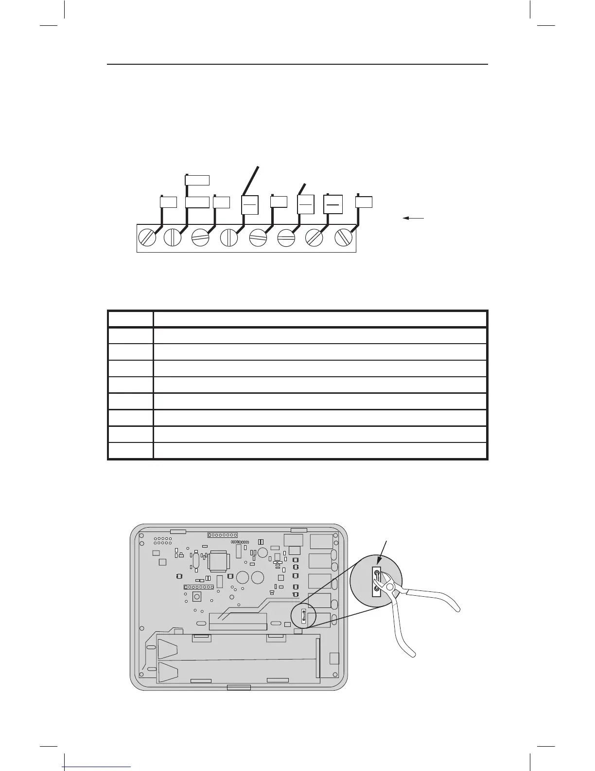
Figure 7. Dual Transformer HVAC System Thermostat Terminal Connections
Connect the wires from the HVAC system to the corresponding terminals on the thermostat back
terminal block. Use the table below as a guideline for connecng the wires.
Wire Terminal
Y2 Connect to the Y2 terminal (2-stage systems only)
Y or Y1 Connect to the Y1 terminal
G Connect to the G terminal
COOL Rc Connect to RC terminal
C Connect to C terminal (Cooling System C Wire, NOT Heang System C Wire)
HEAT Rh Connect to RH terminal
W or W1 Connect to W1 terminal
W2 Connect to W2 terminal (2-stage system only)
IMPORTANT! FOR SEPARATE RC/RH SYSTEMS, THE INTERNAL RC=RH JUMPER
MUST BE CUT ON THE BACK OF THE THERMOSTAT’S PRINTED CIRCUIT BOARD—
(See Figure 8).
Figure 8. Internal RC=RH Jumper
RC=RH JUMPER
CUT JUMPER FOR
DUAL TRANSFORMER
SYSTEMS ONLY
Y2
Y1
G
RC
C
RH
W1
W2
W
C
G
STANDARD
Y2
Y1
G
R
C
R
W1 O
HEAT PUMP
(STICKER LABELED WIRES)
REFERENCE
STANDARD
TERMINALS
Rc
Rh
HEATING SYSTEM R WIRE
COOLING SYSTEM R WIRE
Y2
W2
Y
OR
Y1
R
R
W1