Do you have a question about the NUTOOL MC550 and is the answer not in the manual?
Details on how to correctly connect the mains plug to the product, ensuring safety and proper function.
Basic safety precautions to reduce the risk of fire, electric shock, and personal injury.
Details about the product's 2-year guarantee, including coverage and exclusions.
Details about the product's 2-year guarantee, including coverage and exclusions.
Comprehensive safety instructions for operating the power tool safely and ensuring longevity.
Instructions on how to prevent accidental starting by unplugging the tool.
General safety instructions for operating the power tool safely and ensuring longevity.
Comprehensive safety instructions for operating the power tool safely and ensuring longevity.
Guidance on inspecting the power tool for damage or misalignment before use.
Instructions on preventing accidental starting by ensuring tools are disconnected.
Instructions on preventing accidental starting by ensuring tools are disconnected.
Comprehensive safety instructions for operating the power tool safely and ensuring longevity.
Covers preventing shocks from earthed surfaces, safe use of power cords, and extension cords.
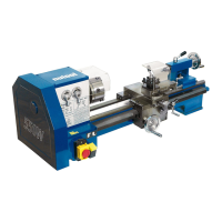
Identification and description of the lathe's parts and controls, referencing Figure 1.
Identification and description of the lathe's parts and controls, referencing Figure 1.
List of the machine's technical specifications.
Guidance on determining the proper and stable location for the machine.
Detailed steps for fitting and removing the 3-jaw self-centering chuck.
Instructions on how to change the chuck jaws, including correct order and fitting.
Details on the operation of the emergency stop switch and its safety cover.
Details on the operation of the emergency stop switch and its safety cover.
Details on the operation of the emergency stop switch and its safety cover.
Measures to protect against electric shock from contact with earthed surfaces.
Measures to protect against electric shock from contact with earthed surfaces.
Details on the operation of the emergency stop switch and its safety cover.
General instructions for operating the lathe.
Detailed steps for fitting and removing the 3-jaw self-centering chuck.
Details on the operation of the emergency stop switch and its safety cover.
Instructions on how to change the chuck jaws, including correct order and fitting.
Details on the operation of the emergency stop switch and its safety cover.