LPC2468 IRD Kit 1.2 Quick Start Guide, rev. 1.0 Page 5 of 8
4. Wait a few seconds for the system to power-up and examine the four
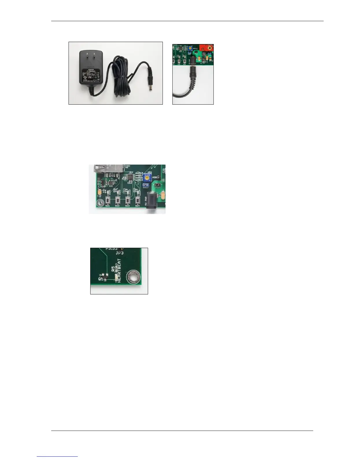
LEDs on the bottom left side of the base board above the 4 push button
switches. They should be blinking ON from left to right and then OFF
from left to right. By adjusting AD0 (VR1), you can adjust the rate of the
blinking LEDs.
5. The Heartbeat LED (bottom right corner of base PCB) should be blinking at a 1Hz
rate.
The following LEDs should be ON:
1. 5VPWR (Red LED located bottom middle of Base Board)
2. 3V3_PWR (Red LED located bottom middle of Base Board)
3. USB_PWR (Green LED located bottom right of Base Board)

 Loading...


