HeatWater.com | WaterService@nyle.com | (800) 777-6953 | Rev. IM-E360-060523 HeatWater.com | WaterService@nyle.com | (800) 777-6953 | Rev. IM-E360-060523
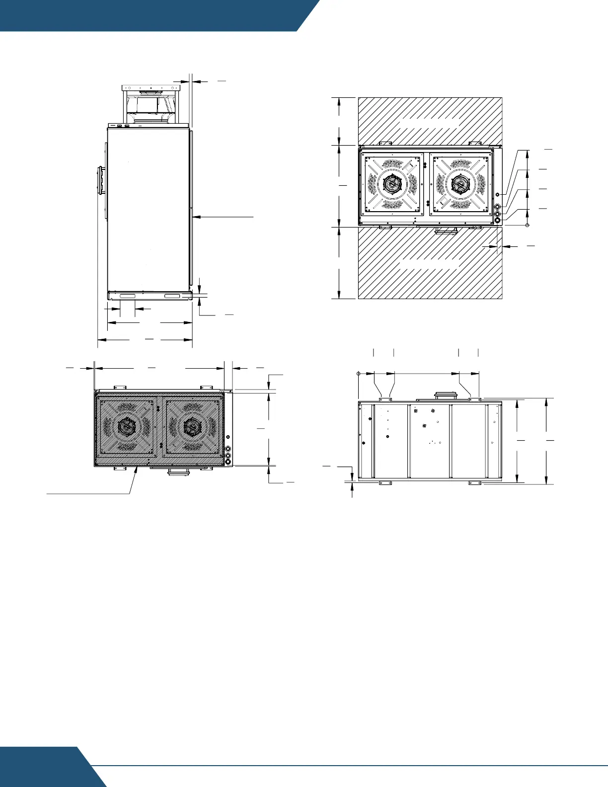
Physical Specifications & Clearances
12
2
1
2
"
24"
36"
41
1
8
"
0"
2
5
8
"
5
3
4
"
9
1
4
"
15
3
8
"
TOP
CLEARANCE
CLEARANCE
1
2
"
4
1
4
"
2"
1
2
"
37
5
8
" O.D.
67
1
2
" O.D.
TOP
DISCHARGE DUCT
COLLAR
40"
1
3
8
"
44
5
8
"
1
5
8
"
7"
AIR FLOW
LEFT
41
3
4
"
7
8
"
43
1
2
"
0"
11
1
2
"
15
3
4
"
56
1
2
"
60
3
4
"
BOTTOM
D1-Dimensional Information
Clearance Note 1:
Unit is designed to be installed with zero side clearance, and all typical service items are serviceable from the front.
However, defrost heaters would need to pull out to the side if replaced. Units may be installed with successive
units oset 6” to the rear to allow the evaporator mounted heaters to pull from the unit right side, or in the unlikely
event of element failure the unit could be temporarily disconnected and moved.
Clearance Note 2:
Bottom clearance to the ground varies by project requirements, and is driven by height required for any necessary
condensate drain pitch. Free discharge (unpiped) condensate applications are not generally recommended.
See “Water and Condensate Piping” section for more information about piped and free discharge condensate
applications.
Clearance Note 3:
If vibration transmission and/or seismic activity is a concern for your installation, account for the additional height
of vibration isolation or seismic measures as recommended by a qualified engineer.
Clearance Note 4:
Top clearance required for fan installation/removal. If fans are installed prior to mounting and unit can be moved to
replace fans in the event of failure, this can reduce to 1” clearance.