HeatWater.com | WaterService@nyle.com | (800) 777-6953 | Rev. IM-E360-060523 HeatWater.com | WaterService@nyle.com | (800) 777-6953 | Rev. IM-E360-060523
Installation: Control Wiring
38
Contacts labelled “Dry” are intended to switch power from external
sources. DO NOT APPLY EXTERNAL POWER to any contact that
is not “Dry”. Equipment damage and system failure can result from
applying power to a powered contact. Follow all power specs for each
contact.
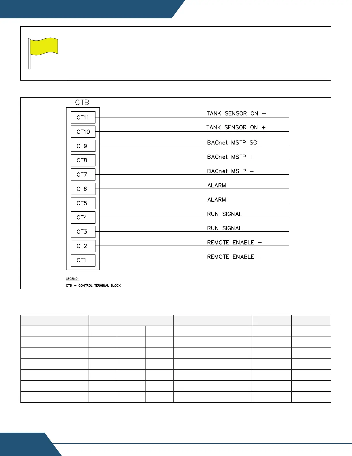
D11-Control Wiring Connections
Control Wire Access conduit in the top of the heat pump is a 3/4” female thread termination
Contact Terminals Wire Type Power Rating
Remote Enable CT1 CT2 -- Any 24Vdc --
Run Signal CT3 CT4 -- Any Dry 4A/24V
Alarm Status CT5 CT6 -- Any Dry 4A/24V
Reserved BMS**
CT7 CT8 CT9 Stranded/Shielded Variable --
Tank Sensor 1 CT10 CT11w -- Stranded/Shielded -- 10k
Reserved OAS**
CT12 CT13 -- Stranded/Shielded -- 10k
Service Mode* 24v i7 -- Any 24Vdc 10k
*Service Mode enables access to Diagnose and Configure screens. Jump terminals for access
**Reserved terminals used by optional accessories and/or internal wiring. See accessory
instructions.
Table 6: Control Wiring Specifications