HeatWater.com | WaterService@nyle.com | (800) 777-6953 | Rev. IM-E360-060523
Installation: Control Wiring
39
Additional notes for individual wired control points:
Remote Enable Contacts: When “External Demand” mode is enabled during
configuration, these contacts will place a heat demand on the heat pump when
an external controller closes a set of dry contacts. No tank sensor is wired to the
heat pump in this mode. In “Tank Sensor” mode, these contacts can be jumped, or
this can be used as a permission signal by external dry contact controls to allow/
disallow compressor operation.
Run Signal Contacts: This dry set of contacts close whenever a heat demand is
present. External devices that need to run in response to the heat pump can use
this as a trigger, such as louver motors and/or booster pumps.
Alarm Status Contacts: This dry set of contacts close whenever the compressor
will not run because of lockout, outdoor temperature, or defrost. Backup heat
sources can use this as an enable trigger.
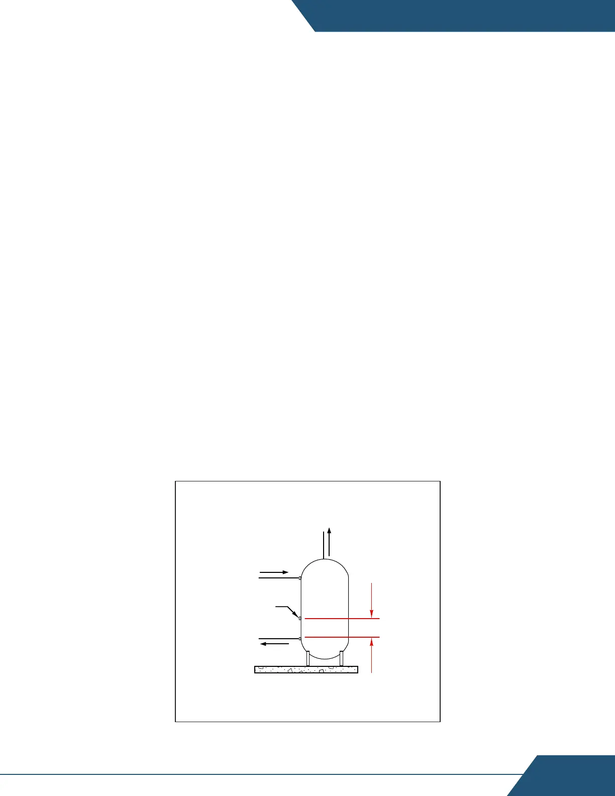
Tank Sensor 1: When “Tank Sensor” mode is enabled during configuration, this
sensor input allows the heat pump to monitor and control the tank temperature.
Take care that the Tank sensor is installed such that the “Minimum Tank Cycle
Volume” or greater volume is between the sensor location and the heat pump
intake water pipe near the bottom of the storage tank. Always use the maximum
tank cycle volume possible for a given installation to minimize cycle losses and
equipment wear.
D12 - Tank Sensor Installation
To Heat Pump
Tank sensor or
Aquastat