32
2. General Information
2.1 On-Board Diagnostics (OBD) II
2.2 Diagnostic Trouble Codes (DTCs)
OBD II Diagnostic Trouble Codes are codes that are stored by the on-
board computer diagnostic system in response to a problem found in
the vehicle. These codes identify a particular problem area and are
intended to provide you with a guide as to where a fault might be
occurring within a vehicle. OBD II Diagnostic Trouble Codes consist
of a five-digit alphanumeric code. The first character, a letter,
identfies which control system sets the code. The other four
characters, all numbers, provide additional information on where the
DTC originated and the operating conditions that caused it to set.
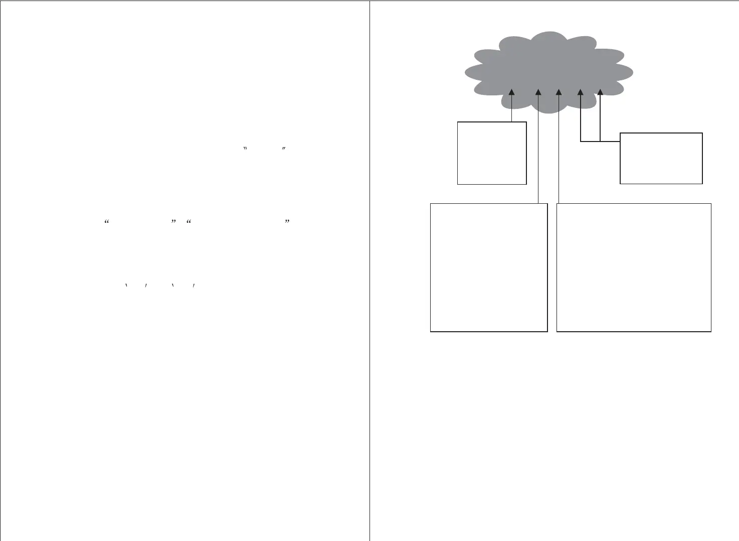
Here below is an example to illustrate the structure of the digits:
1) Whether the Malfunction Indicator Light (MIL) is
commanded on or off ;
2) Which, if any, Diagnostic Trouble Codes (DTCs) are stored;
3) Readiness Monitor status.
The first generation of On-Board Diagnostics (called OBD I) was
developed by the California Air Resources Board (ARB) and
implemented in 1988 to monitor some of the emission control
components on vehicles. As technology evolved and the desire to
improve the On-Board Diagnostic system increased, a new generation
of On-Board Diagnostic system was developed. This second generation
of On-Board Diagnostic regulations is called OBD II
The OBD II system is designed to monitor emission control systems
and key engine components by performing either continuous or
peridic tests of specific components and vehicle conditions. When a
problem is detected, the OBD II system turns on a warning lamp
(MIL) on the vehicle instrument panel to alert the driver typically by
the phrase of Check Engine or Service Engine Soon . The system
will also store important information about the detected malfunction
so that a technician can accurately find and fix the problem. Here
below follow three pieces of such valuable information:
DTC Example
P0202
Systems
B=Body
C=Chassis
P=Powertrain
U=Network
Identifying specific
malfunctioning
section of the
systems
Code Type
Generic (SAE):
P0, P2, P34-P39
B0, B3
C0, C3
U0, U3.
P1, P30-p33
B1, B2
C1, C2
U1, U2
Manufacturer Specific:
Sub-systems
1= Fuel and Air Metering
2= Fuel and Air Metering
3= Ignition System or Engine Misfire
4= Auxiliary Emission Controls
5= Vehicle Speed Control and Idle
Controls
6= Computer Output Circuits
7= Transmission Controls
8= Transmission Controls
2.3 Location of the Data Link Connector (DLC)
The DLC (Data Link Connector or Diagnostic Link Connector) is the
standardized 16-cavity connector where diagnostic scan tools
interface with the vehicle
,
s on-board computer. The DLC is usually
located 12 inches from the center of the instrument panel (dash),
under or around the driver
,
s side for most vehicles. If Data Link
Connector is not located under dashboard, a label should be there
telling location. For some Asian and European vehicles, the DLC is
located behind the ashtray and the ashtray must be removed to access
the connector. If the DLC cannot be found, refer to the vehicle,s
service manual for the location.