USB2000 Specifications
USB2000 Operating Instructions 9
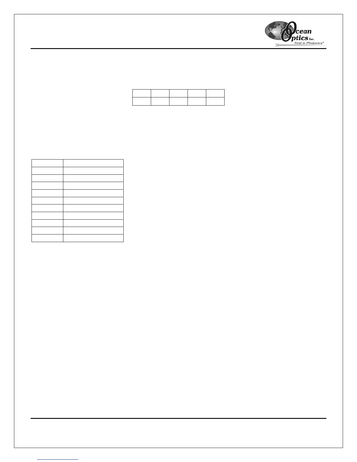
10-Pin Accessory Connector Pinout Diagram
When facing the 10-pin Accessory Connector on the USB2000, pin numbering is as follows:
10 8 6 4 2
9 7 5 3 1
Figure 2-3: 10-Pin Accessory Connector Pinout Diagram
10-Pin Accessory Connector – Pin Definitions
The following table contains information regarding the function of each pin in the USB2000’s 10-pin accessory
connector:
Pin # Description
1 V
USB
or 5V in
2 RS232 Tx
3 RS232 Rx
4 Lamp Enable
5 Continuous Strobe
6 Ground
7 External Trigger In
8 Single Strobe
9 I
2
C SCL
10 I
2
C SDA
10-Pin J2 Accessory Connector – Part Number and Compatibility
The part numbers for the USB2000 Spectrometer 10-pin accessory connector are as follows:
• The connector is Samtec model IPT1-105-01-S-D-RA.
• The mating right-angle connector is Samtec model IPS1-105-01-S-D-RA.
If you are customizing your USB2000 Spectrometer system or configuring an External Triggering configuration,
you may need these part numbers to complete your setup.