Appendix B
USB2000 Operating Instructions 37
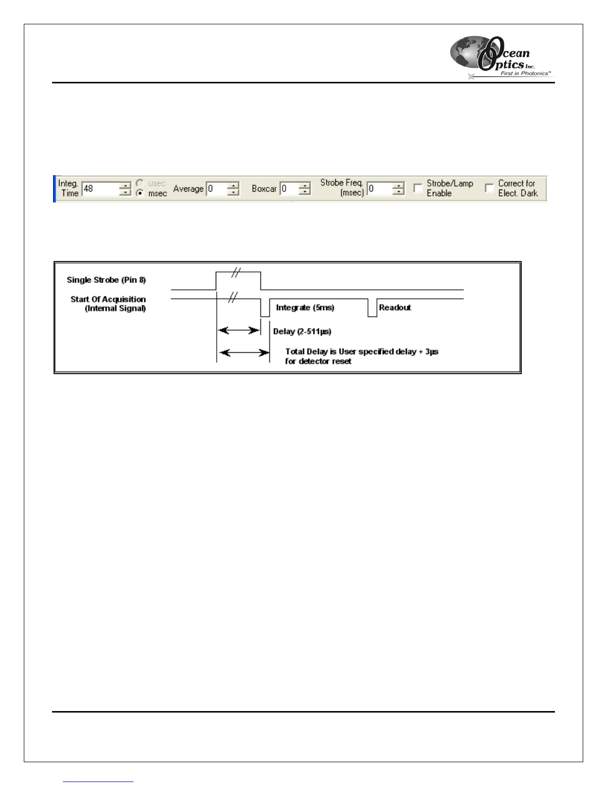
8. Enable Single Strobe output by checking the Strobe Enable check box (See Figure B-1 on the following
page).
The strobe signal is a rising edge trigger signal that is TTL High for the entire delay period. See Figure B-2
for a timing diagram.
The USB2000-FLG is now configured for operation in Variable Delay Mode.
Figure B-1: The Acquisition Parameters Toolbar.
Note the location of the Strobe Freq (entered in
µ
s) and Strobe/Lamp Enable options.
Figure B-2: Timing Diagram for Variable Delay Mode