B6250/B6500 User’s Guide> 7
B
ASIC
O
PERATIONS
M
AIN
C
OMPONENTS
AND
T
HEIR
F
UNCTIONS
S
TANDARD
C
ONFIGURATION
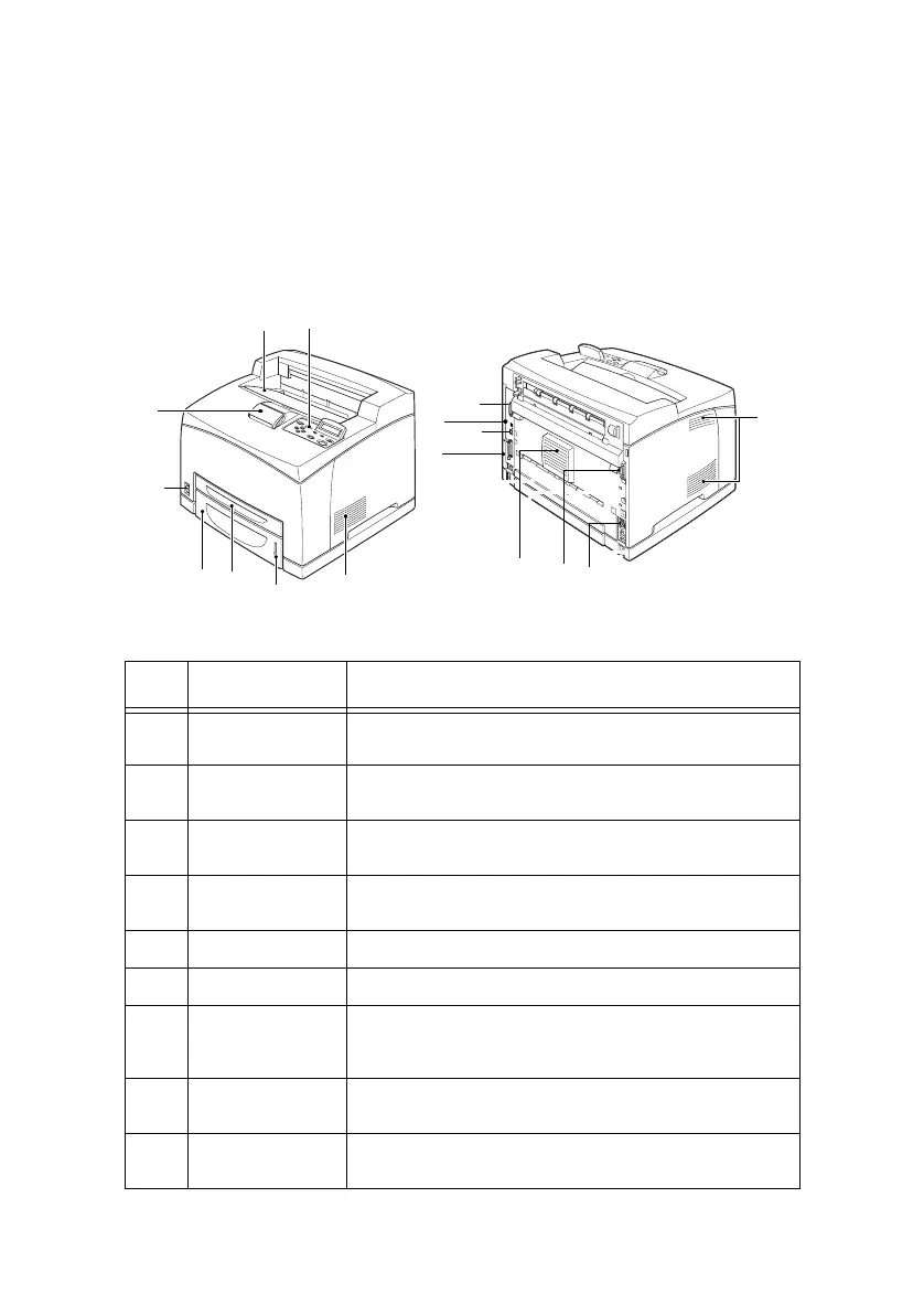
NO. NAME DESCRIPTION
1 Centre output
tray
Print jobs are output here with the printed side facing
down.
2 Control panel Consists of the essential operation buttons, indicators
and display.
3 Ventilation hole Releases heat to prevent the interior of the printer
from heating up.
4 Paper meter A meter to check the amount of remaining paper.
Attached to the 550 tray.
5 Tray 1 Sets the 150 tray.
6 Tray 2 Sets the 550 tray.
7 Power switch Switches the power of the printer on and off. Pressing
the switch to the <|> position switches it on and
pressing it to the <0> position switches it off.
8 Paper stopper Raise this when printing on paper larger than Letter/
A4 size.
9 Duplex unit
connector
For connecting the optional duplex unit.
1
2
8
7
3
6
5
4
13
12
11
3
3
9
10
14