EasyManua.ls Logo

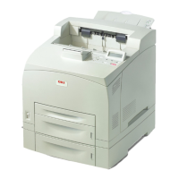
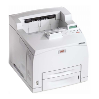
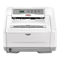
Oki B6200 User Manual

Oki B6200
679 pages
To Next Page IconTo Next Page
Page #1 background imageLoading...
Page #1 background image
Oki Data CONFIDENTIAL
B6200/B6300
Maintenance Manual
070111D

Table of Contents

Other manuals for Oki B6200

Questions and Answers:

Oki B6200 Specifications

General IconGeneral
ColorNo
Duplex printingYes
Print technologyLaser
Maximum resolution1200 x 1200 DPI
Time to first page (black, normal)10.2 s
Print speed (black, normal quality, A4/US Letter)24 ppm
Internal memory128 MB
Processor modelPowerPC
Maximum internal memory640 MB
Sound power level (standby)50.3 dB
Total input capacity400 sheets
Total output capacity500 sheets
Maximum print size210 x 297 mm
Media weight (tray 1)60 - 216 gsm
Paper tray media typesLabels, Transparencies
Non-ISO print media sizesExecutive (184 x 267mm), Legal (media size), Letter (media size)
ISO A-series sizes (A0...A9)A4, A5, A6
ISO B-series sizes (B0...B9)B5
Maximum ISO A-series paper sizeA4
Power requirements230VAC +/-10%, 50/60Hz +/-2%
Compatible operating systemsWindows 98, 98SE, ME, NT4.0, 2000, XP
Maximum duty cycle75000 pages per month
Operating temperature (T-T)5 - 35 °C
Operating relative humidity (H-H)15 - 80 %
Weight and Dimensions IconWeight and Dimensions
Dimensions (WxDxH)422 x 455 x 324 mm

Summary

Cautions for operation

2. Marks giving caution

4. Safety

4.1 Power source

Precautions related to the printer's power supply during maintenance.

4.2 Driving units

Safety precautions related to the printer's driving mechanisms.

4.3 High-temperature units

Safety precautions for servicing high-temperature components like the fuser.

4.4 Laser beams

Safety warnings and information regarding the laser beam system.

5. Installation

5.1 Power source

Guidelines for connecting the printer to an electrical outlet.

5.2 Ground

Procedures for establishing a proper ground connection for the laser printer.

5.5 Installation Procedures

Step-by-step guide for installing the printer and its components.

6. Disassembly

1. Progressing with the Troubleshooting

1.1 Flow of Troubleshooting

Outlines the process for diagnosing and recovering from troubles.

1.3 Cautions for Service Operations

Important safety warnings and procedures for service operations.

2. Level 1 FIP

2.3 Error/Status Code List

List of error and status codes with their corresponding FIP references.

3. Level 2 FIP

3.1 Level 2 FIP

Explanation of Level 2 Fault Isolation Procedures for detailed troubleshooting.

4. Error Code FIP

4.1 Level 1 FIP

Fault Isolation Procedures for Level 1 errors, categorized by error code.

1. How to Use Diag (C/E) Mode

1.1 Roles of Control Panel in Diag (C/E) Mode

Explains the functions of the LCD and control panel keys for diagnostic operations.

1.3 How to Enter Diag (C/E) Mode

Step-by-step instructions for entering the diagnostic mode.

1.6 How to Select Diag Code

Steps for selecting and executing diagnostic codes.

2. Service Data

2.4 DC131 NVM R/W

Procedures for reading from and writing to NVM.

1. Removal and Replacement Procedures

1.1 Before starting service work

Crucial steps and precautions before commencing any service or removal operations.

1.2 Prohibited matter

Components that should not be removed to maintain printer alignment.

RRP1. Cover

RRP1.4 COVER TOP (PL1.1.7), OPERATION PANEL (PL1.1.1)

Procedures for removing and replacing the top cover and operation panel.

RRP1.6 SWITCH I/L ASSY (PL1.1.11)

Procedure for removing and replacing the interlock switch assembly.

Chapter 1 Troubleshooting

1. Progressing with the Troubleshooting

Guidance on how to efficiently proceed with troubleshooting a printer issue.

2. Level 1 FIP

First step for trouble diagnosis, isolating various troubles including error codes.

3. Level 2 FIP

Detailed fault diagnostic procedures based on symptoms.

4. Error Code FIP

Fault Isolation Procedures for Level 1 errors, categorized by error code.

Chapter 2 Operation of Diagnostic

1. How to Use Diag (C/E) Mode

Instructions on navigating and using the diagnostic mode via the control panel.

Chapter 3 Removal and Replacement Procedures (RRPs)

1. Removal and Replacement Procedures

General overview of parts removal and replacement procedures.

Chapter 6 Principle of Operation

6. Control

Explanation of printer controls, including paper size and fuser control.

Chapter 7 Wiring Diagrams and Signal Information

Chapter 8 Printer Specifications

2. Electrical Characteristics

Information on power supply types and power consumption specifications.

3. Mechanical Characteristics

Specifications for dimensions and mass of printer components.

8. Safety/Environmental Protection

Lists applicable safety and environmental standards for the printer.

9. Print Image Quality

Specifications and troubleshooting for print image quality.

Related product manuals