44015503TH Rev. 1
147 /
Oki Data CONFIDENTIAL
5. MAINTENANCE MENUS
• The PU serial number is shown at Printer Serial Number in the header of the
printer’s configuration report (a Menu Map) output from the printer. After the
PU serial number is changed, it can be checked by printing the report from
the printer.
(
2) Switching to Shipping mode
When the engine control board is replaced with a new one, the printer is placed
in the Factory mode. Switch the printer to the Shipping mode.
• To switch, use the Factory/Shipping mode window described in section
2.4.1.1.2.2 of an applicable Maintenance Utility operation manual, section
2.4.1.1.2 about PU board setup functionality.
Note! R
eplacing the EEPROM (the engine control board) with a new one clears life
information about consumables, including the belt, toner and image drums.
Note that, until the consumables are replaced, this makes differences between
their displayed consumed and consumed lives. Such life information cleared
is as shown below. Upon replacement of the consumables, the information
(counts) except Total Sheets Fed are cleared, and differences between the
counts and consumed lives of the consumables are cleared.
Item Description Detail
Fuser Unit A fuser life count. A value converted on an A4
page basis from the number
of pages printed to date after
installation of a fuser unit.
Belt Unit A belt unit life count. A value converted on an A4
page basis from the number
of pages printed to date after
installation of a belt unit.
Image Drum Unit Black
Image Dr
um Unit Yellow
Image Drum Unit
Magenta
Image Drum Unit Cyan
Each the life count of
the image drum unit
associated with this
option.
A value converted on an A4
page basis from the number
of pages printed to date after
installation of the image drum
unit associated with this option.
Total Sheets Fed A printer life count. The total number of sheets fed.
Prints Black
Pr
ints Yellow
Print Magenta
Prints Cyan
Each the number of
pages printed with the
image drum associated
with this option.
The number of pages printed
after installation of a new
image drum unit.
5.4.2 EEPROM setup after CU board replacement
The user-set information on the CU board must be maintained on the replacement CU board
for the board. For operation to maintain:
Install the EEPROM directly from the board to the replacement board (see below).
Copy information from the EEPROM by using Maintenance Utility (see section 5.2).
Steps
and cannot be used when a service call 40 (an EEPROM error) occurs. In such
a case, reset network information, including an IP address, after the board is replaced with
the replacement one.
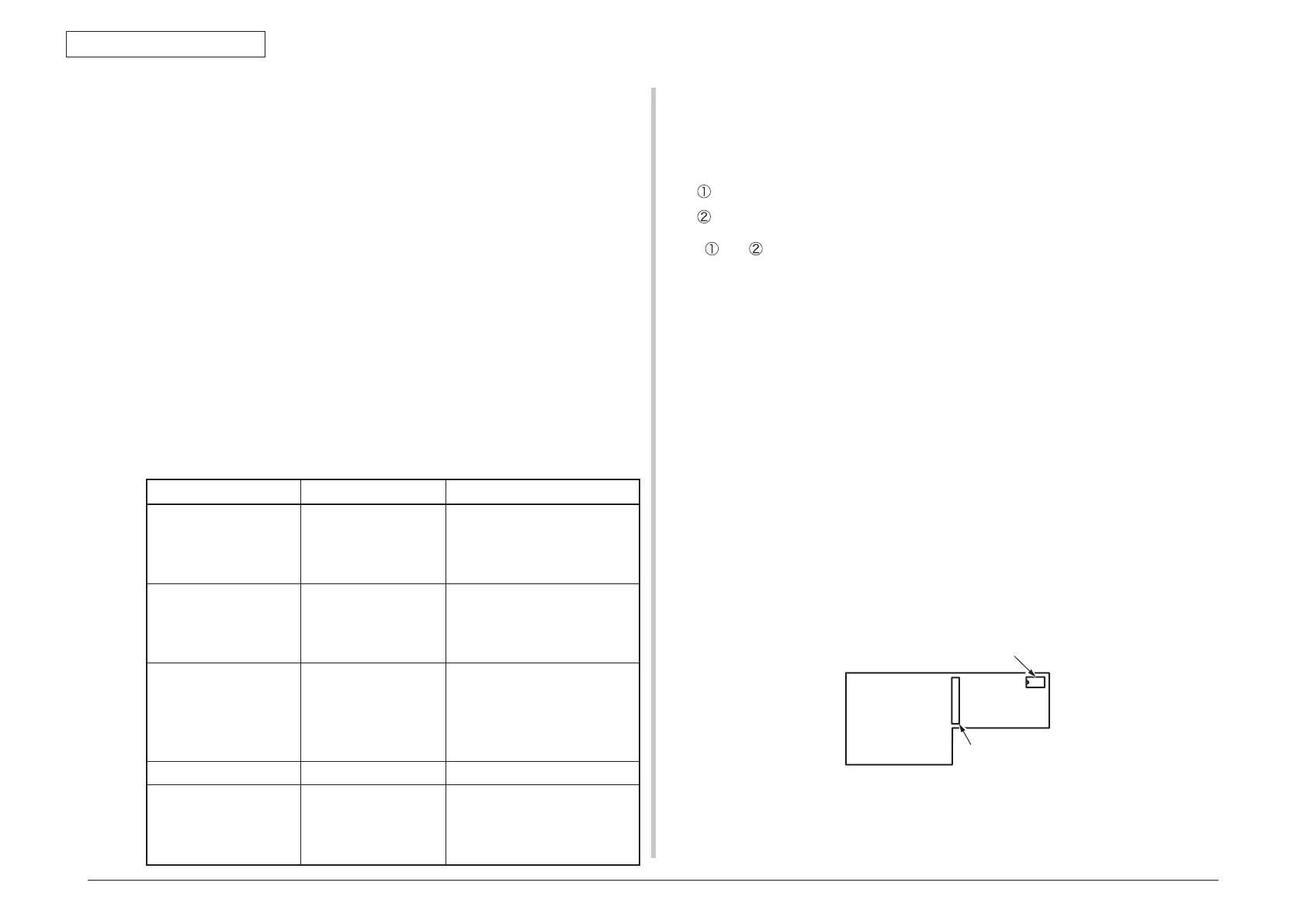
EEPROM replacement after CU board replacement
The EEPROM on the CU board is installed by using an IC socket. Replace the EEPROM
with new one as follows:
1
. Remove the EEPROM and the MAC address label from the CU board.
2. Insert a screw driver between the EEPROM and IC socket and remove the lead of
the EEPROM so as that the lead is not bent.
3
. Being sure that the EEPROM and a new CU board to install it are oriented in the
same direction, install the EEPROM on the new board.
4
. Place the MAC address label on the new board.
5. Print a configuration report (a Menu Map) and make sure that the MAC address on
the Menu Map is the same as that on the MAC address label.
 Loading...