44952001TH Rev.2
2-15
Oki Data CONFIDENTIAL
2. DESCRIPTION OF OPERATION
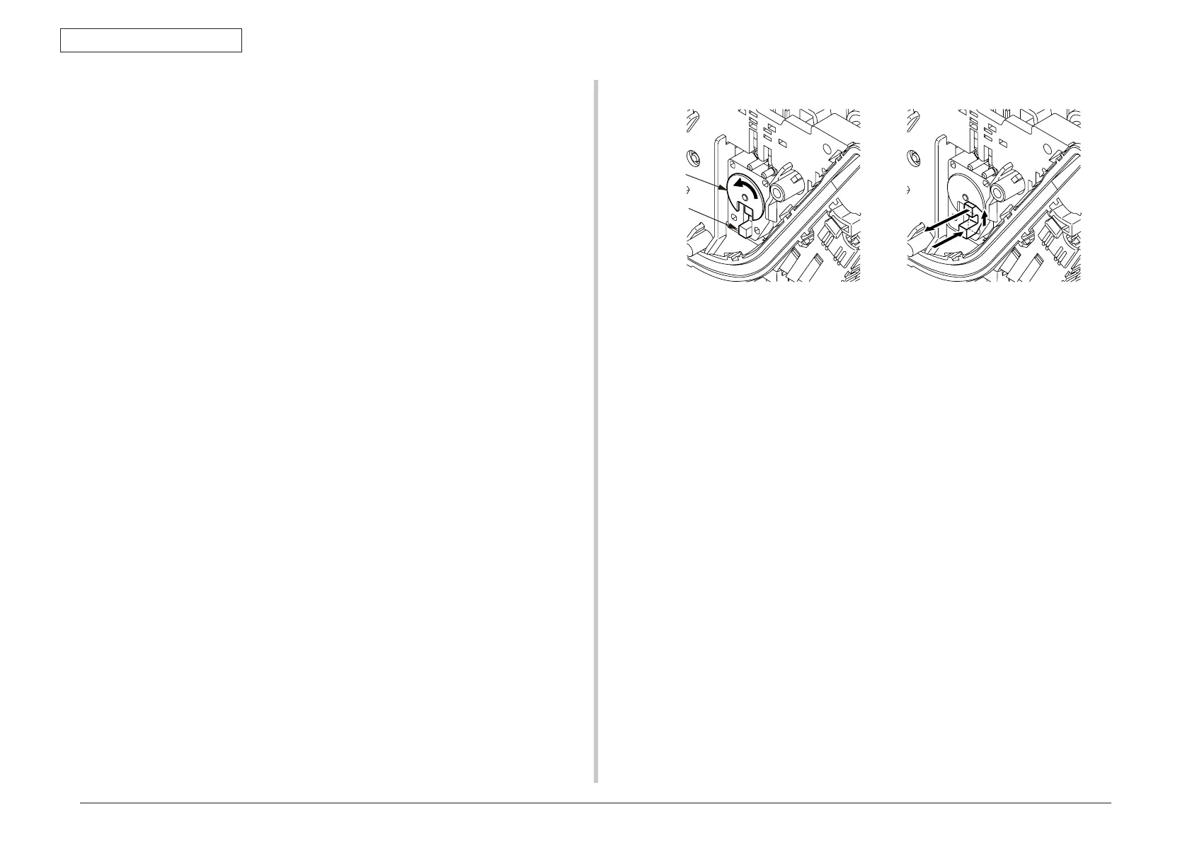
Prism
Shielding plate
Error checking methods and remedies
The density correction test function among the other self-diagnostic functions is employed
to check errors. (Section 5.3.2.7)
Remedies for different errors
• CALIBRATIONERR,DENSSENSORERR
Check 1: If the above indication appears, check the connected state of the sensor
cable.
If the connected state is found abnormal, restore it to the normal state.
Check 2: Check to see whether the sensor surface is stained with toner, paper
dust or any other foreign matter.
If it is found stained, wipe it clean.
If no problem was found by the checks 1 and 2, there is a problem with the circuit.
Replace each of the density sensor, the CU/PU board and the connector cable one
by one and check that no error will occur again.
• DENSSHUTTERERR
Check 3: Check to see whether the sensor shutter opens and closes normally, by
the MOTOR & CLUTCH TEST of the self-diagnostic function. If the shut-
ter operates imperfectly, replace the shutter unit.
• DENSIDERR
Check 4: Take out the ID units and examine them to see if the drum surface has
any abnormal toner smudge.
Replace the LED head (out-of-focus), or replace any ID units with any ab-
normality.
To test-operate a new ID unit, use the Fuse Keep Mode of the mainte-
nance menu.
Principle of toner sensor detection
Toner LOW is detected by a toner sensor (Reflection sensor) installed inside each of the
printers. A shielding plate is mounted inside each ID and rotates in synchronization with
toner agitation.
Moreover,eachIDhasashuttertted.Eachshutterissynchronizedwiththeoperationlever
of the relevant toner cartridge, and the toner sensor can detect that the toner cartridge has
been loaded properly. Detection may not take place normally, and a toner sensor error may
be issued, if a shielding plate or toner sensor is stained with toner, or if an ID unit and the
relevant toner sensor do not remain exactly opposite to each other in their positions.
Principle of the toner counter
After image data is developed to binary data that the printers can print, the LSI counts the
data as the number of print dots. The amount of toner consumed is calculated from that
count value, and the remaining amount of toner is thus indicated. As opposed to this, toner
LOW detection by a toner sensor is implemented when the amount of toner remaining
inside an ID unit physically decreases to below a certain level.
Principles of ID, belt, and fuser counters
ID counter: One count represents the value that results from dividing the amount
ofrotationofadrumbythreewhenthreeA4-sizesheetsareprinted
continuously.
Belt counter: One count represents the value that results from dividing the amount
ofrotationofthebeltbythreewhenthreeA4-sizesheetsareprinted
continuously.
Fuser counter: One count is registered when paper is shorter than the length of
Legal 13-inch paper. When paper is longer than that, a count to add is
determined by the number of times that the Legal 13-inch paper length is
exceeded. (Rounding up of decimal fractions)